


Groundsmaster 4000--D/4010--DHydraulic System Page 4 -- 142
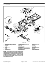
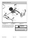
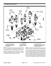
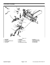
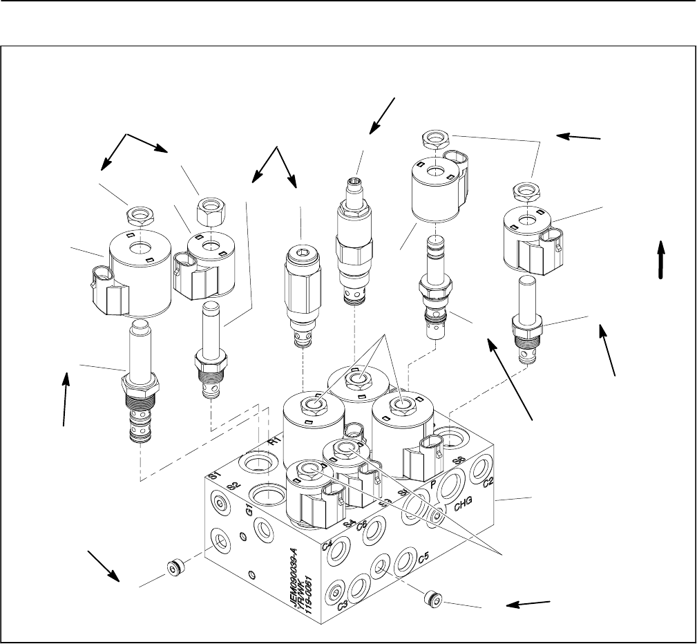
Lift/Lower Manifold Service
1. Lift/lower manifold body
2. Solenoid valve (S4, S6 & S9)
3. Solenoid coil (5 used)
4. Nut (8 used)
5. Relief valve (RV2)
6. Relief valve (RV1)
7. Solenoid valve (S1)
8. Nut
9. Solenoid coil (4 used)
10. Solenoid valve (S2, S3, S7 & S8)
11. #4 zero leak plug with O--ring
12. Solenoid valve (S5)
Figure 112
2
3
6
8
9
10
11
1
5
7
12
4
3
3
4
2
10
11
UP
20 ft--lb
(27 N--m)
25 ft--lb
(34 N--m)
5 ft--lb
(6.7 N--m)
20 ft--lb
(27 N--m)
20 ft--lb
(27 N--m)
20 ft--lb
(27 N--m)
5 ft--lb
(6.7 N--m)
25 ft--lb
(34 N--m)
20 ft--lb
(27 N--m)
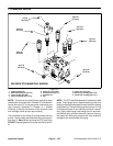
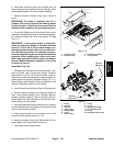
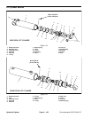
NOTE: The ports on the lift/lower manifold are marke d
for easy identification of components. Example: S1 is
solenoid valve S1 and P is the gear pump connection
port (see Hydraulic Schematic in Chapter 10 -- Foldout
Drawings to identify the function of the hydraulic lines
and cartridge valves at each port location).
NOTE: The lift/lower manifold assembly includes sev-
eralzeroleak plugs. These plugs have ataperedsealing
surface on the plug head that is designed to resist vibra-
tion induced plug loosening. The zero leak plugs also
have an O--ring as asecondary seal. If zero leak plug re-
moval is necessary, lightly rap the plug head using a
punch and hammer before using an allen w rench to re-
move the plug: the impact will allow plug removal with
less chance of damage to the socket head of the plug.