


Groundsmaster 4000--D/4010--DHydraulic System Page 4 -- 134
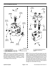
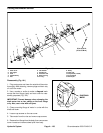
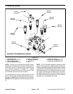
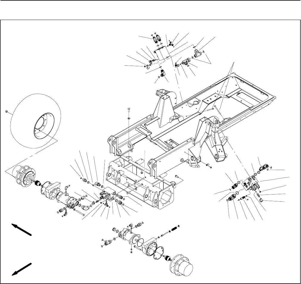
PTO Manifold
1. Hydraulic PTO manifold (front deck)
2. Quick fitting (1 used per manifold)
3. Flange nut
4. O--ring
5. Hydraulic fitting
6. O--ring
7. O--ring
8. O--ring
9. Hydraulic adapter
10. Straight fitting
11. Cap screw (2 used per manifold)
12. Dust cap
13. Hydraulic adapter
14. Hydraulic PTO manifold (LH deck)
15. Hydraulic fitting
16. Hydraulic PTO manifold (RH deck)
17. 90
o
hydraulic fitting
18. Hydraulic adapter
19. O--ring
20. 90
o
hydraulic fitting
21. O--ring
22. R--clamp
23. O--ring
24. Hydraulic tee fitting
25. O--ring
26. Hydraulic fitting
27. 45
o
hydraulic fitting
Figure 106
FRONT
RIGHT
12
1
2
3
4
5
8
6
9
11
10
7
20
19
18
17
25
26
22
23
27
24
7
16
14
12
13
15
3
3
6
6
6
7
5
8
8
8
2
4
21
21
21
5
2
19
18
19
19
18
23
4
21
12
11
21
25
8
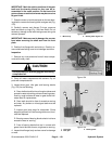
NOTE: The ports on the manifold are marked for easy
identification of components. Example: S is the deck so-
lenoid valve and P1 is a gear pump connection port (see
Hydraulic Schematic in Chapter 10 -- Foldout Drawings
to identify the function of the hydraulic lines and car-
tridge valves at each port).