


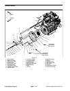


Groundsmaster 4000--D/4010--DHydraulic System Page 4 -- 6
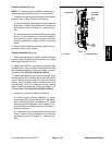
Hydraulic Hose and Tube Installation (O--Ring Face Seal Fitting)
1. Make sure threads and sealing surfaces of the hose/
tube and the fitting are free of burrs, nicks, scratches or
any foreign material.
2. As a preventative measure against leakage, it is rec-
ommended that the face seal O--ring be r eplaced any
time the connection is opened. Make sure the O--ring is
installedandproperlyseated in the fitting groove. Lightly
lubricate the O--ring with clean hydraulic oil.
3. Place the hose/tube against the fitting body so that
the flat face of the hose/tubesleeve fully contacts theO--
ring in the fitting.
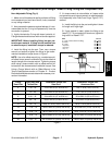
4. Thread the swivel nut onto the fitting by hand. While
holding the hose/tube with a wrench, use a torque
wrench to tighten the swivel nut to the recommended
installation torque shown in Figure 5. This tightening
process will require the use of an offset wrench (e.g.
crowfoot wrench). Use of an offset wrench will affect
torque wrench calibration due to the effective length
change of the torque wrench. Tightening torque when
usingatorque wrench with an offsetwrenchwillbelower
than the listed installation torque (see Using a Torque
Wrench with an Offset Wrench in the Torque Specifica-
tions section of Chapter 2 -- Product Records and Main-
tenance).
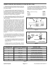
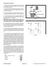
5. If a torque wrench is not available or if space at the
swivel nut prevents use of a torque wrench, an alternate
method of assembly is the Flats From Wrench Resist-
ance (F.F.W.R.) method (Fig. 2).
A. Using a wrench, tightenthe swivel nutonto thefit-
ting until light wrench resistanceis reached(approxi-
mately 30 in--lb).
B. Mark the swivel nut and fitting body. Hold the
hose/tube with a wrench to prevent it from turning.
C. Use a secondwrench to tightenthe nut to the cor-
rect Flats From Wrench Resistance (F.F.W.R.). The
markingsonthenutand fitting body will verify thatthe
connection has been properly tightened.
Size F.F.W.R.
4 (1/4 in. nominal hose or tubing) 1/2 to 3/4
6 (3/8 in.) 1/2 to 3/4
8 (1/2 in.) 1/2 to 3/4
10 (5/8 in.) 1/2 to 3/4
12 (3/4 in.) 1/3 to 1/2
16 (1 in.) 1/3 to 1/2
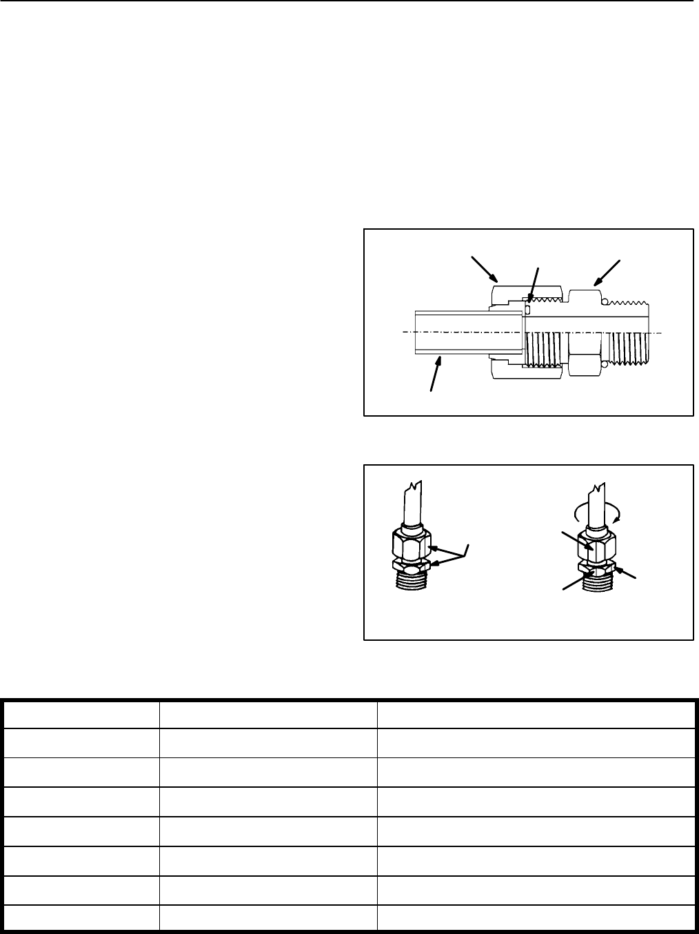
Figure 3
O--ring
Fitting Body
Swivel Nut
Tube or Hose
Figure 4
Final
AT WRENCH RESISTANCE
Position
Mark Nut
and Fitting
Initial
Position
Extend Line
AFTER TIGHTENING
Body
Fitting Dash Size Hose/Tube Side Thread Size Installation Torque
4 9/16 -- 18 18to22ft--lb(25to29N--m)
6 11/16 -- 16 27to33ft--lb(37to44N--m)
8 13/16 -- 16 37to47ft--lb(51to63N--m)
10 1--14 60 to 74 ft --lb (82 to 100 N--m)
12 13/16--12 85 to 105 ft --lb (116 to 142 N--m)
16 17/16--12 110 to 136 ft--lb (150 to 184 N--m)
20 1 11/16 -- 12 140 to 172 ft--lb (190 to 233 N--m)
Figure 5