


Groundsmaster 4000--D/4010--D Page 5 -- 29 Electrical System
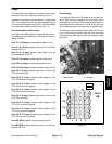
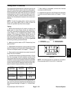
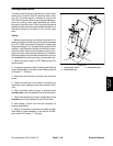
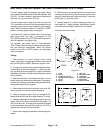
Parking Brake Switch
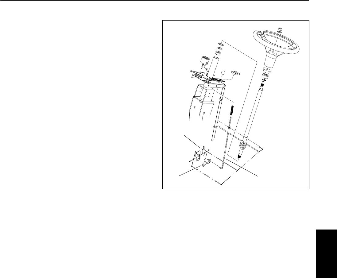
The switch used for the parkingbrake isa normally open
switch that is located under the s teering tower cover
(Fig. 32). The brake switch is used as an input for the
TEC--5002 controller. Whentheparkingbrakeis not ap-
plied, the parking brake pawl depresses the switch
plunger to close the switch. When the parking brake is
applied, the parking brake pawl is positioned away from
the switch plunger so the switch is in its normal, open
state.
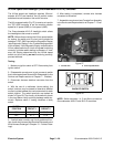
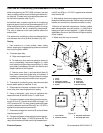
Testing
1. Before disconnecting the parking brake switch for
testing, the switch and its circuit wiring should be tested
as a TEC--5002 input with the Diagnostic Display (see
Diagnostic Display in theTroubleshootings ection ofthis
chapter). If the Diagnostic D isplay verifies that the park-
ing brake switch and circuit wiring are functioning cor-
rectly,no further switch testingis necessary. If, however,
the Display determines that the brake switch and circuit
wiring are not functioning correctly, proceed with test.
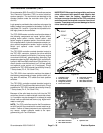
2. Make sure ignition switch is OFF. Remove key from
ignition switch.
3. Locate parking brake switchfortesting (see Steering
Tower Disassembly in the Service and Repairs section
of Chapter 7 -- Chassis).
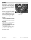
4. Disconnect wire harness connector from the brake
switch.
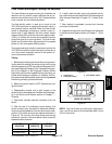
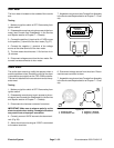
5. Check the continuity of the switch by connecting a
multimeter (ohms setting) across the connector termi-
nals.
6. When the brake switch plunger is extended there
should not be continuity between the switch terminals.
7. When the brake switch plunger is depressed, there
should be continuity between the switch terminals.
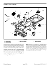
8. After testing, connect wire harness connector to
parking brake switch.
9. Secure all removed components to steering tower
(see Steering Tower Assembly in the Service and Re-
pairs section of Chapter 7 -- Chassis).
1. Parking brake switch
2. Parking brake rod
3. Parking brake pawl
Figure 32
1
3
2
Electrical
System