


Groundsmaster 4000--D/4010--D Page 5 -- 21 Electrical System
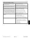
Fuses
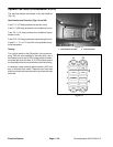
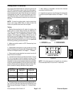
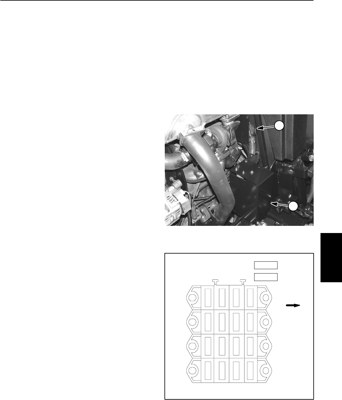
The fuse blocks are located in the power center under
the hood on the right side of the machine (Fig. 17).
In addition to the fuses in the fuse blocks, a 40 amp fuse
(F5--1) is included in the wire harness to protect the pull
coil circuit for the engine run s olenoid. This fuse resides
in a fuse holder near the s tarter motor (Fig. 17).
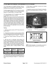
Fuse Identification and Function
Use Figure 18 to identify each individual fuseand its cor-
rect amperage in the fuse block. The fuses have the fol-
lowing functions.
FuseF1--1(20amp)protects engine starter circuit.
Fuse F1--3 (10 amp) protects light circuit on Ground-
smaster 4010--D.
FuseF1--4(10amp)protects signal light circuit on
Groundsmaster 4010--D.
FuseF2--2(10amp)protects operator seat circuit.
FuseF2--3(10amp)protects power point circuit.
FuseF2--4(10amp)protects main power supply c ircuit.
Fuse F3--1 (2 amp) protects logic power circuit to the
TEC--5002 controller.
Fuse F3--2 (7.5 amp) protects power supply for the
TEC--5002 controller outputs.
Fuse F3--3 (7.5 amp) protects power supply for the
TEC--5002 controller outputs.
Fuse F3--4 (7.5 amp) protects power supply for the
TEC--5002 controller outputs.
Fuse F4--1 (2 amp) protects logic power circuit to the
TEC--5001 controller.
Fuse F4--2 (7.5 amp) protects power supply for the
TEC--5001 controller outputs.
Fuse F4--3 (7.5 amp) protects power supply for the
TEC--5001 controller outputs.
Fuse F4--4 (7.5 amp) protects power supply for the
TEC--5001 controller outputs.
FuseM1(60A)protects engine glow plug circuit.
FuseM2(60A)protects operator cab circuit on Ground-
smaster 4010--D.
Fuse Testing
Turn ignition switch to the ON position (do not start en-
gine). With the fuse installed in the fuse block, use a
multimeter to verify that 12 VDC exists at both of the ter-
minal test points on the fuse. If 12 VDC exists at one of
the fuse test points but not at the other, the fuse is faulty.
If necessary, make sure that ignition switch is OFF and
key is removed from switch. R emove fuse from fuse
block and check that fuse has continuity across the fuse
terminals.
Figure 17
1. Power center 2. Fuse F5--1
1
2
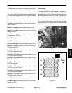
Figure 18
F1
F2
1234
F3
F4
FRONT
2A
7.5 A
7.5A
7.5A
2A
7.5A
7.5A
7.5A
10A
10A
10A
20A
OPTION
M1 (60A)
M2 (60A)
10A
OPTION
10A
Electrical
System