


Groundsmaster 4000--D/4010--D Page 5 -- 23 Electrical System
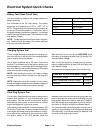
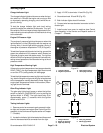
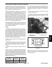
Warning Lights
Charge Indicator Light
Thechargeindicatorlightshould come on when the igni-
tion switch is in ON with the engine not running or with
an improperly operating charging circuit while the en-
gine is running.
To test the charge indicator light and circuit wiring,
ground the white wire attached to alternator. Turn igni-
tionswitch to ON; thechargeindicator light shouldillumi-
nate indicating correct operation of the electrical wiring
to the alternator.
Engine Oil Pressure Light
The engine oil pressure light should come on when the
ignition switch is in the ON position with the engine not
running. Also, it should light with the engine running if
the engine oil pressure drops below 7 PSI (0.5 kg/cm
2
).
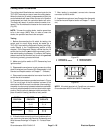
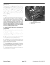
To test theoilpressurelight and circuitw iring, ground the
green wire attached to oil pressure switch located on
right side of engine near the starter motor. Turn ignition
switchtoON;theoil pressure light should illuminate indi-
cating correct operation of the electrical wiring to the oil
pressure switch.
High Temperature Warning Light
If the engine coolant temperature rises to approximately
220
o
F (105
o
C), the high temperature light should come
on and the PTO (cutting decks) will disengage.
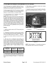
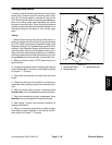
To test the high temperature warning lightandcircuitwir-
ing, start the engine and ground the gray wire attached
to the temperature sender attached to water flange on
engine (see Temperature Sender in this section). Warn-
ing light should illuminate.
Glow Plug Indicator Light
The glow plug light should come on when the ignition
switch is placed in ON/PREHEAT prior to placing the
ignition switch in START. The light should stay lit for
approximately seven (7) s econds while the ignition
switch is left in ON.
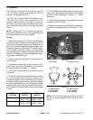
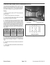
Testing Indicator Lights
1. Remove control arm covers to gain access to indica-
tor light and harness connectors (see Control Arm Dis-
assembly in the Service and Repairs section of Chapter
7 -- Chassis).
2. Locate the indicator light tobe tested anddisconnect
the wire harness electrical connector from the light.
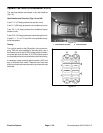
3. Apply 12 VDC to terminals 1A and 2A (Fig. 22).
4. Ground terminals 1B and 2B (Fig. 22).
5. Both indicator lights should illuminate.
6. Connect wire harness electrical connector to the in-
dicator light.
7. Install control arm cover to machine (see Control
Arm Assembly in the Service and Repairs section of
Chapter 7 -- Chassis).
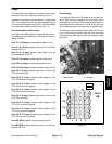
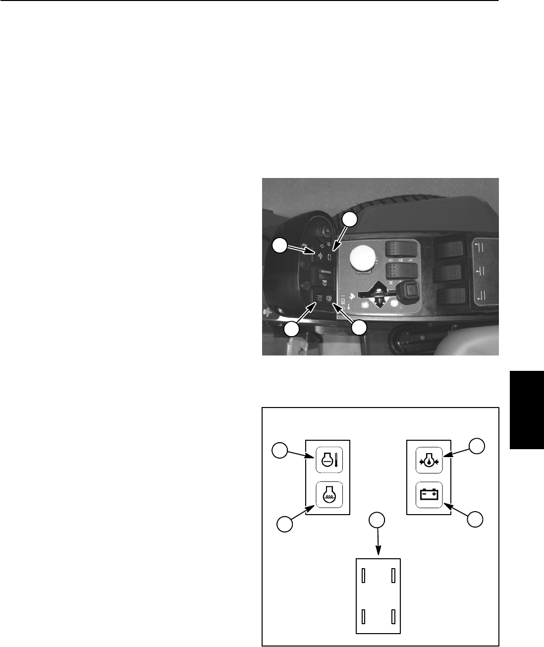
1. Charge indicator
2. Engine oil pressure
3. High temp warning
4. Glow plug indicator
Figure 21
1
2
3
4
Figure 22
1. Charge indicator
2. Engine oil pressure
3. High temp warning
4. Glow plug indicator
5. Warning light back
1A
2A2B
1B
4
3
2
1
5
Electrical
System