


Groundsmaster 4000--D/4010--DPage 6 -- 6Axles, Planetaries and Brakes
2. Apply gasket sealant tosealing s urfaces of new gas-
ket (item 18). Apply gasket to brake assembly.
3. Install brake assembly onto machine, aligning
splined brake shaft with input shaft on planetary wheel
drive.
4. Secure brake assembly to planetary assembly with
four (4) flange head screws (item 9). Tighten screws in
a crossing pattern to a torque from 75 to 85 ft--lb (101
to 115 N--m).
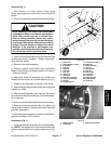
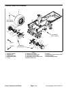
5. Secure brake link assembly to pull rod on brake as-
sembly, frame bracket and brake lever (Fig. 2). Brake
link end should be completely threaded onto pull rod be-
fore tightening jam nut.
6. Install new O--ring on hydraulic wheel motor. Install
wheel motor and torque cap screws from 75 to 85 ft--lb
(101 to 115 N--m).
WARNING
Failure to maintain proper wheel lug nut torque
could result in failure or loss of wheel and may
result in personal injury.
7. Install wheel assembly.
8. Lower machine to ground. Torque lug nuts from 85
to 100 ft--lb (115 to 135 N--m).
9. Make sure drain plug is installed in bottom of brake
assembly. Fill planetary wheel drive/brake assembly
with SAE85W--140 gear lube. Capacity is approximate-
ly 16 fl. oz. (0.47 liters) per wheel.
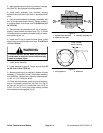
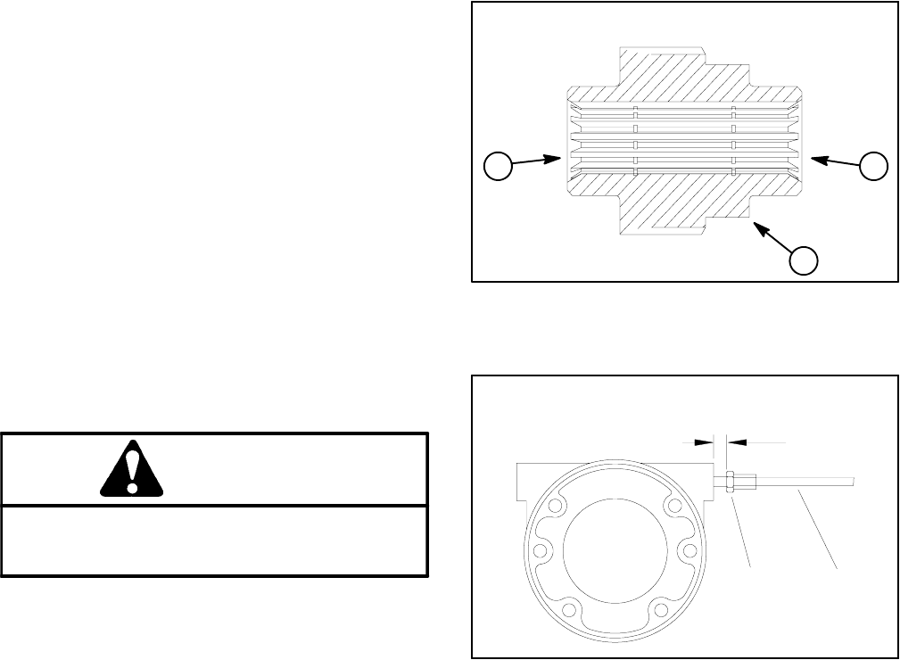
10.Check and adjust brake cables for proper brake op-
eration. If necessary, adjust hex link (item 12 in Fig. 2)
so that pull rod jam nut is positioned from 0.470” to
0.530” (12.0 to 13.4 mm) from brake casting surface
when brakes are disengaged (Fig. 5).
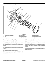
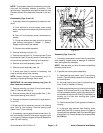
1. Splined brake shaft step
2. Hydraulic motor end
3. Planetary assembly end
Figure 4
1
2
3
1. Pull rod jam nut 2. Brake link
Figure 5
1
2
0.470” to 0.530”
(12.0 to 13.4 mm)