


Groundsmaster 4000--D/4010--D Page 7 -- 17 Chassis
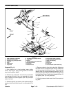
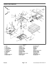
Removal (Fig. 15)
1. Park machine on a level surface, lower cutting
decks, stop engine, apply parking brake and remove
key from the ignition switch.
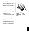
2. Disconnect seat electrical connector from machine
wire harness (Fig. 16).
3. Support console arm assembly to prevent it from
shifting.
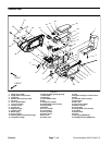
4. Remove flange nut (item 29) and carriage screw
(item 32) that secure support bracket (item 30) to sup-
port channel (item 31).
5. Remove cap screw (item 37) that secures console
arm support (item 35) to coupler nut (item 38).
6. Remove cap screw (item 33), flat washers (item 20),
spacer (item 36) and seat belt latch (item 39) from seat
and console arm support (item 35).
IMPORTANT: Make sure to not damage the electri-
cal harness, control cable or other parts while mov-
ing the console arm assembly.
7. Carefully move console arm assembly away from
seat.
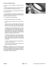
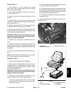
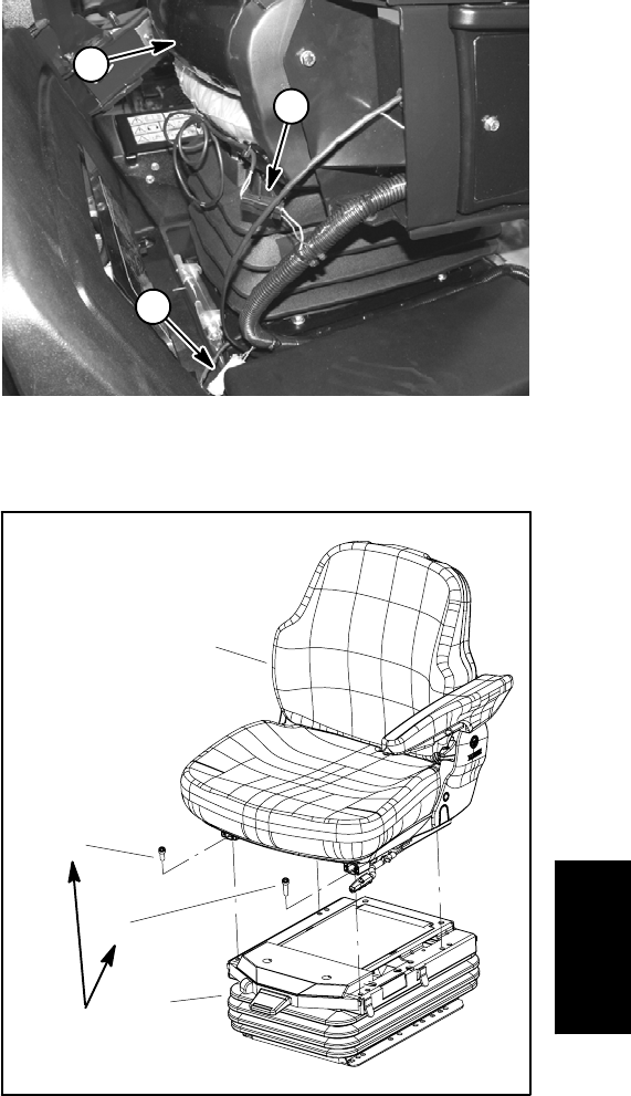
8. Remove four (4) torx head screws that secure seat
to seat suspension (Fig. 17). Note that the screw near
theseatadjustmenthandleislongerthanthe otherthree
(3) screws.
9. Lift seat from seat suspension and remove from ma-
chine.
NOTE: Refer to Operator Seat Suspension in this sec-
tion if seat suspension service is necessary.
Installation (Fig. 15)
1. Carefully position seat to seat suspension.
2. Secure seat to seat suspension with four (4) torx
head screws (Fig. 17). Make sure that longer screw is
positioned near the seat adjustment handle. Torque
screws 18 ft--lb (25 N --m).
IMPORTANT: Make sure to not damage the electri-
cal harness, control cable or other parts while mov-
ing the console arm assembly.
3. Position and secure console arm assembly to seat.
Install all fasteners before fully tightening them.
A. Secure support bracket (item 30) and support
channel (item 31) with flange nut (item 29) and car-
riage screw (item 32).
B. Secure console arm support (item 35) to coupler
nut (item 38) with cap screw (item 37).
C. Place flat washer (item 20), seat belt latch (item
39) and spacer (item 36) between seat and console
arm support (item 35). Secure w ith cap screw (item
33) and second flat washer (item 20).
D. Fully tighten all fasteners to secure console arm
assembly to seat.
4. Connect seat electrical connector to machine wire
harness (Fig. 16).
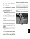
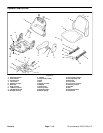
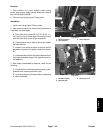
1. Operator seat
2. Seat switch connector
3. Suspension connector
Figure 16
1
2
3
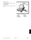
1. Seat
2. Suspension assembly
3. Screw (M8x12) (3 used)
4. Screw (M8x16)
Figure 17
2
3
1
4
18 ft--lb
(25 N--m)
Chassis