


Groundsmaster 4000--D/4010--DPage 5 -- 38Electrical System
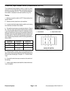
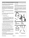
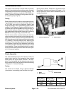
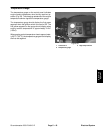
Traction Neutral Switch
The traction neutral switch is closed when the traction
pedalisinthe neutral positionandopenswhen the pedal
is depressed in either direction (forward or reverse). The
neutral switch is used as an input to the TEC--5002 con-
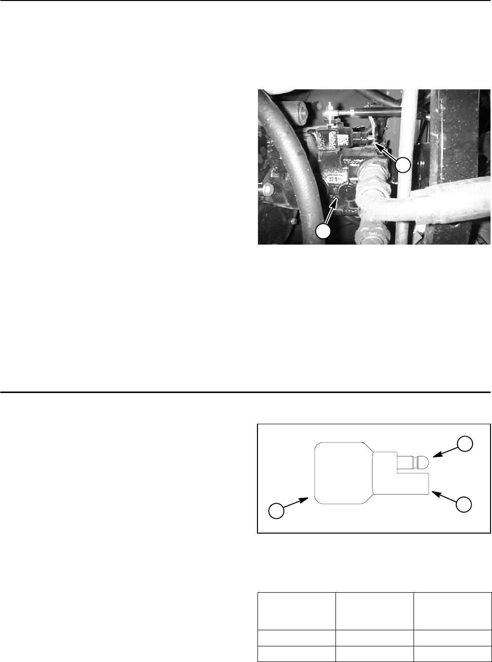
troller. The switch is located on the right side of the pis-
ton (traction) pump (Fig. 48).
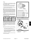
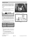
Testing
Before disconnecting the traction neutral switch for test-
ing, the switch and its circuit wiring should be tested as
a TEC--5002 input with the Diagnostic Display (see
Diagnostic Display in theTroubleshootings ection ofthis
chapter). If the Diagnostic Display verifies that the neu-
tral switch and circuit wiring arefunctioning correctly, no
further switch testing is necessary. If, however, the Dis-
play determines that the neutral switch and circuitwiring
are not functioning correctly, proceed with test.
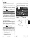
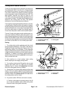
Test the neutral switch by disconnecting the wire har-
ness connector from the switch and connecting a multi-
meter (set to ohms) across the two (2) switch terminals.
Withtheengineturned off,slowlypush the tractionpedal
in a forward or reverse direction while watching the
multimeter. There should be indications that the traction
neutral switch is opening (high resistance) and closing
(no resistance). Allow the traction pedal to return to the
neutral position. There should be continuity (no resist-
ance)acrosstheswitchterminals when the tractionped-
al is in the neutral position.
See the Eaton Model 72400 Servo Controlled Piston
Pump Repair Information at the end of Chapter 4 -- Hy-
draulic System for neutral switch disassembly and as-
sembly procedures.
1. Piston pump (bottom) 2. Neutral switch
Figure 48
1
2
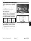
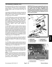
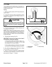
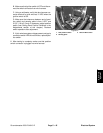
Diode Assembly
The Groundsmaster engine wire harness contains a
diode that is used for circuit protection from voltage
spikes when the engine starter solenoid is de--ener-
gized. The diode plugs into the wiring harness near the
enginestarter motor (see EngineWireHarness Drawing
in Chapter 10 -- Foldout Drawings).
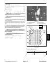
Testing
The diode can be tested using a digital multimeter
(diode test or ohms setting) and the table to the right.
Figure 49
1. Diode
2. Male terminal
3. Female terminal
1
2
3
Multimeter
Red Lead (+)
on Terminal
Multimeter
Black Lead (--)
on Terminal
Continuity
Female Male YES
Male Female NO