


Groundsmaster 4000--D/4010--DPage 5 -- 6Electrical System
Troubleshooting
CAUTION
Remove all jewelry, especially rings and
watches, before doing any electrical trouble-
shooting or testing. Also, disconnect the battery
cables unless the test requires battery voltage.
For effective troubleshooting and repairs, you must
have a good understanding of the electrical circuits and
components used on this machine (see Chapter 10 --
Foldout Drawings).
If the machine has any interlock switches by--passed,
reconnect the switches for safety and efficient trouble-
shooting.
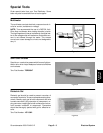
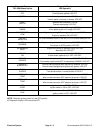
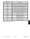
NOTE: Use the Diagnostic Display (see Special Tools
in this chapter) to test Toro Electronic Controller inputs
and outputs when troubleshooting an electrical problem
on your Groundsmaster.
Diagnostic Display
Groundsmaster 4000--D and 4010--D machines are
equipped with two (2) Toro Electronic Controllers (TEC)
which control machine electrical functions. The control-
lers monitor various input switches (e.g. ignition switch,
seat switch, neutral switch) and energize outputs to ac-
tuate solenoids or relays for the requested machine
function.
For the TEC to control the machine as desired, each of
the inputs (switches and sensors) and outputs (sole-
noids and relays) must be connected and functioning
properly.
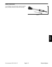
The Diagnostic Display (see Special Tools in this chap-
ter) is a tooltohelpthetechnicianverify correctelectrical
functions of the machine.
IMPORTANT: The Diagnostic Display must not be
left connected to the machine. It is not designed to
withstand the environment of the machine’s every
day use. When use oft he DiagnosticDisplay iscom-
pleted, disconnect it from the machine and recon-
nect loopback connector to harnessconnector. The
machine will not operate without the loopback con-
nector installed on the harness. Store the Diagnos-
tic Display in a dry, secure, indoor location and not
on machine.
CAUTION
The interlock switches are for the protection of
the operator and bystanders and to ensure cor-
rect operation of the machine. Do not bypass or
disconnect switches. Check the operation of the
interlockswitchesdaily for proper operation. Re-
place any malfunctioning switches before oper-
ating the machine.
Verify Diagnostic Display Input Functions
1. Park machine on a level surface, lower the cutting
decks, stop the engine and apply the parking brake.
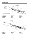
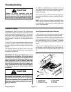
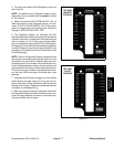
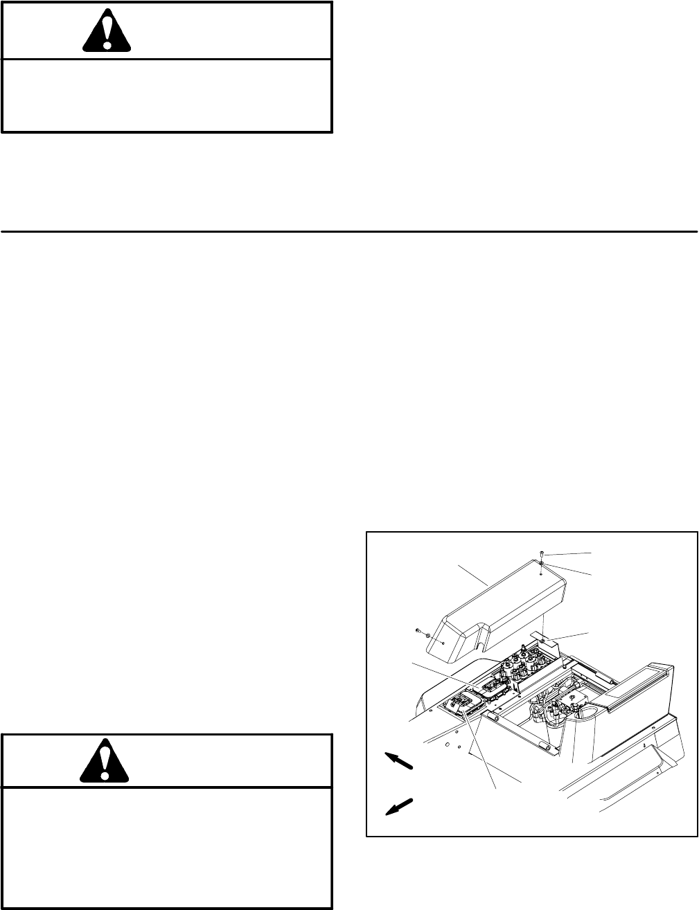
2. Remove the controller cover to allow access to wire
harness loopback connector (Fig. 8). Locate wire har-
ness communication port and loopback connector.
Carefully unplug loopback connector from harnesscon-
nector.
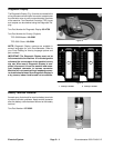
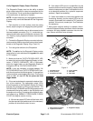
3. Connect the Diagnostic Display connector to the
wire harness connector. Make sure correct overlay de-
cal is positioned on the Diagnostic Display (Figs. 9 and
10).
1. Controller cover
2. Screw (2 used)
3. Flat washer (2 used)
4. U--nut (2 used)
5. TEC--5001
6. TEC--5002
Figure 8
FRONT
RIGHT
2
3
1
4
6
5