


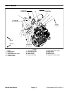

Groundsmaster 4000--D/4010--DPage 3 -- 14Kubota Diesel Engine
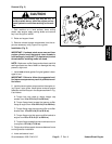
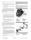
8. Disconnect fuel supply hose from injection pump
(Fig. 13).
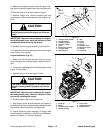
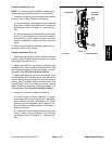
9. Remove throttle cablefromengine (Figs. 13 and14):
A. Remove lock nut that secures throttle cable swiv-
el to speed control lever.
B. Loosen cable clamp and remove throttle cable
from under clamp.
C. Position throttle cable away from the engine.
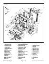
10.Remove fasteners that secure the upper radiator
shroud to the lower shroud and radiator (see Radiator
Removal in this s ection). Position coolant reservoir and
bracket away from the radiator. Remove upper radiator
shroud from machine.
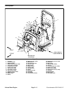
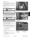
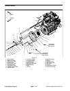
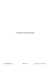
11.Remove cooling fan motor and fan assembly (Fig.
15).
A. To prevent contamination of hydraulic system,
thoroughly clean exterior of fan motor and fittings.
B. Disconnect hydraulic hoses from cooling fan mo-
tor. Put caps or plugs onfittings and hoses to prevent
contamination. Label hydraulic lines for proper as-
sembly.
C. Remove six ( 6) cap screws and flange nuts that
secure fan motor bracket to radiator.
D. Carefully remove fanmotor,fan and motor brack-
et assembly from machine.
12.Remove transport cylinder assembly from engine
mount (Fig. 16). It is not necessary to remove the hy-
draulic hose from the cylinder. Locate and remove cylin-
der spacer from between transport cylinder and engine
mount.
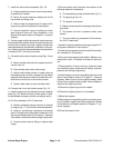
13.On Groundsmaster 4010--D machines:
A. Remove windshield washer reservoir from reser-
voir mount on engine (Fig. 17). Position reservoir
away from engine. Do not remove reservoir mount
from engine.
B. Remove air conditioningcompressor from brack-
ets (see Air Conditioning Compressor Removal in
the ServiceandRepairs section of Chapter 9 -- Oper-
ator Cab). Position compressor away from engine
taking care to not damage compressor or hoses.
Support compressor to make sure it will not fall dur-
ing engine removal.
C. Disconnect coolant hose from fitting on engine
water flange.
IMPORTANT: The hydraulic pump assembly can re-
main in machine during engine removal. To prevent
pump from shifting or falling, make sure to support
pump assembly before mounting fasteners are re-
moved.
14.Support hydraulic pump assembly. Remove fasten-
ers that secure pump assembly to engine (see Pump
Assembly Removal in the Service and Repairs section
of Chapter 4 -- H ydraulic System).
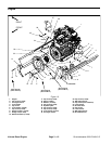
Figure 14
1. Lock nut
2. Throttle cable
3. Cable support
4. Lock nut
5. Washer head screw
6. Cap screw (2 used)
7. Cable clamp
8. Spring washer (2 used)
9. Lock nut
10. Cable swivel
11. Cable stop
2
3
4
8
9
6
7
1
5
10
11
Figure 15
1
2
3
4
5
6
1. Fan
2. Fan motor bracket
3. Fan motor
4. Cap screw (6 used)
5. Flange nut (6 used)
6. Radiator