


2 - 23
SPEC
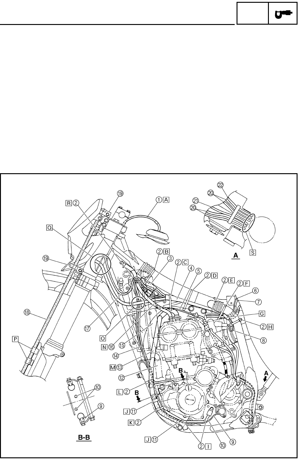
CABLE ROUTING DIAGRAM
EC240000
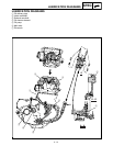
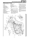
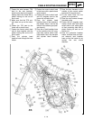
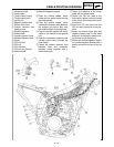
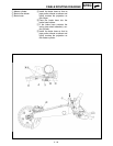
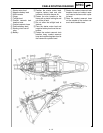
CABLE ROUTING DIAGRAM
1
Fuel tank breather hose
2
Clamp
3
Diode
4
Wire harness
5
Hot starter cable
6
Negative battery lead
7
Starter motor lead
8
TPS (throttle position sen-
sor) lead
9
Neutral switch lead
0
Oil hose
A
Hose holder
B
Radiator hose 4
C
Cylinder head breather hose
D
AC magneto lead
E
Radiator hose 1
F
Oil tank breather hose
G
Lights switch lead
H
Brake hose
I
Hose guide
J
Carburetor breather hose
K
Overflow hose
L
Coolant reservoir tank breather
hose
Å
Insert the fuel tank breather
hose into the hole in the steering
shaft cap.
ı Fasten the diode of the wire har-
ness and rectifier/regulator lead
(at its protecting tube) to the
frame at the white tape for the
diode with a plastic locking tie
and cut off the tie end.
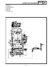
Ç Fasten the wire harness, recti-
fier/regulator lead, coolant res-
ervoir hose and hot starter cable
to the frame with a plastic lock-
ing tie and cut off the tie end.
Î Fasten the wire harness, recti-
fier/regulator lead and coolant
reservoir hose to the frame with
a plastic locking tie and cut off
the tie end.
‰ Fasten the wire harness to the
frame at its white tape with a
plastic locking tie and cut off the
tie end.