


5 - 44
CHAS
HANDLEBAR
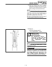
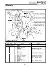
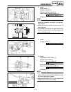
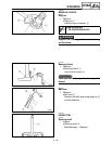
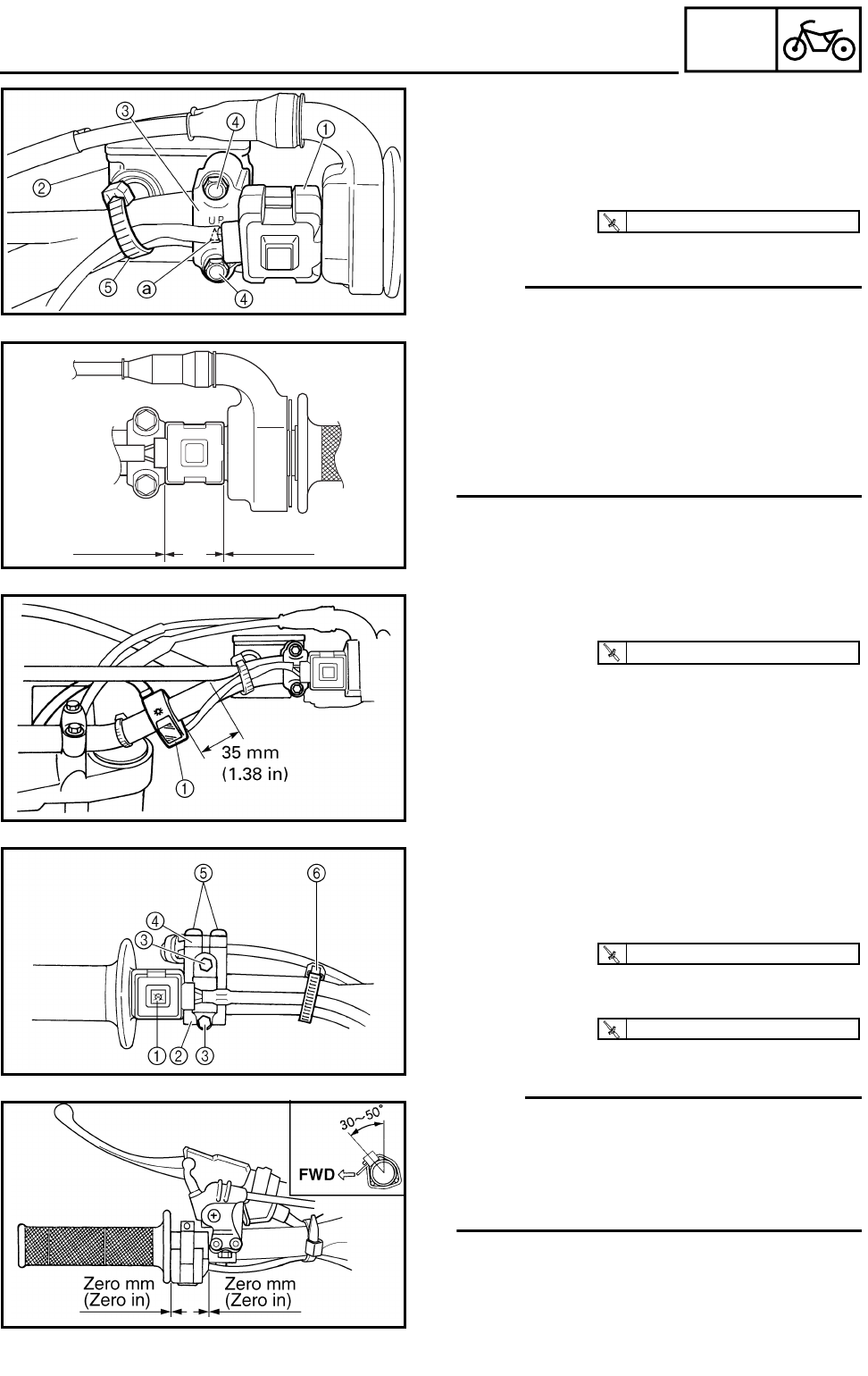
8. Install:
● Start switch 1
● Master cylinder 2
● Master cylinder bracket 3
● Bolt (master cylinder bracket) 4
● Clamp 5
NOTE:
● The start switch and master cylinder bracket
should be installed according to the dimen-
sions shown.
● Install the bracket so that the arrow mark a
faces upward.
● First tighten the bolt on the upper side of the
master cylinder bracket, and then tighten the
bolt on the lower side.
T
R
.
.
9 Nm (0.9 m · kg, 6.5 ft · lb)
Zero mm
(Zero in)
Zero mm
(Zero in)
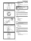
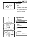
9. Install:
● Lights switch 1
T
R
.
.
2 Nm (0.2 m · kg, 1.4 ft · lb)
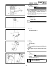
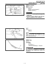
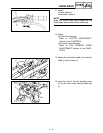
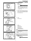
10. Install:
● “ENGINE STOP” button 1
● Clutch lever holder 2
● Bolt (clutch lever holder) 3
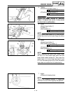
● Hot starter lever holder 4
● Bolt (hot starter lever holder) 5
● Clamp 6
NOTE:
● The “ENGINE STOP” button, clutch lever
holder and clamp should be installed accord-
ing to the dimensions shown.
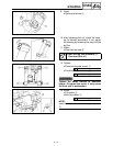
● Pass the “ENGINE STOP” button lead in the
middle of the clutch lever holder.
T
R
.
.
4 Nm (0.4 m · kg, 2.9 ft · lb)
T
R
.
.
4 Nm (0.4 m · kg, 2.9 ft · lb)