


4 - 64
ENG
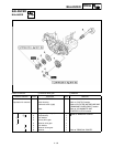
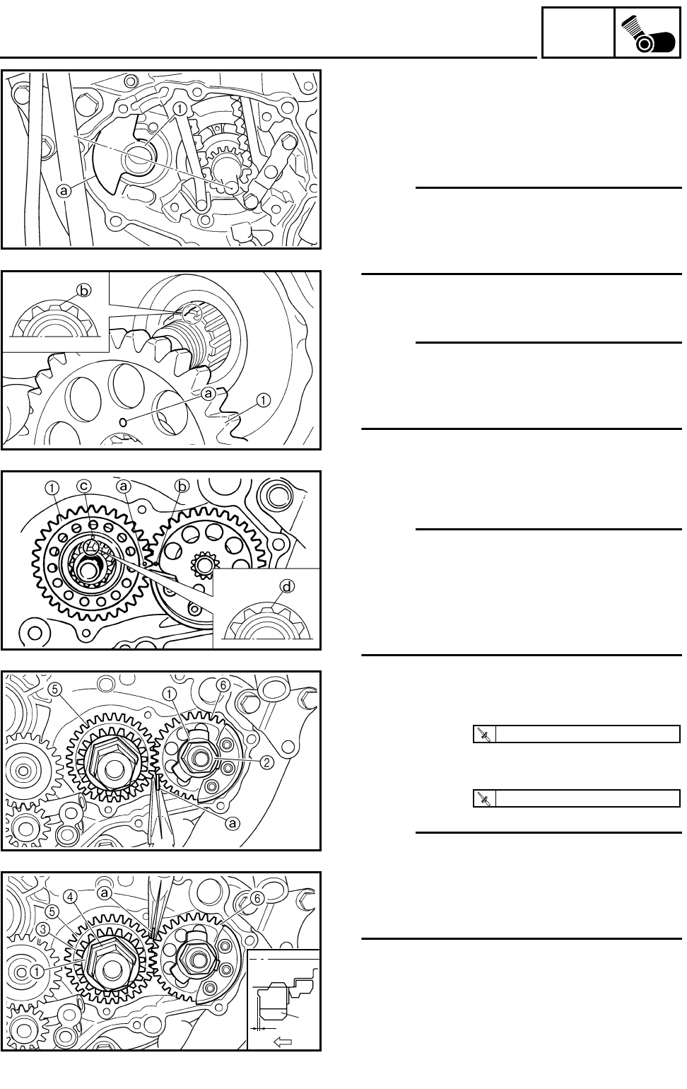
BALANCER
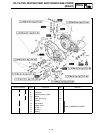
ASSEMBLY AND INSTALLATION
Balancer, balancer drive gear and balancer
driven gear
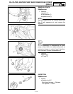
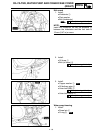
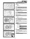
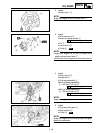
1. Install:
●
Balancer
1
NOTE:
When installing the balancer shaft, align the
center of the balancer shaft weight
a
along
the line connecting the centers of the crank-
shaft and balancer shaft.
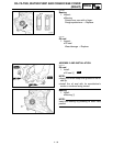
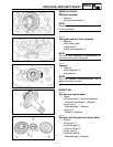
2. Install:
●
Balancer driven gear
1
NOTE:
Install the balancer driven gear onto the bal-
ancer while aligning the punch mark
a
on the
balancer driven gear with the lower spline
b
on the balancer end.
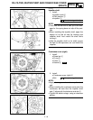
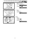
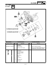
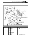
3. Install:
●
Balancer drive gear
1
NOTE:
● Align the punched mark a on the balancer
drive gear with the punched mark b on the
balancer driven gear.
● Align the punched mark c on the balancer
drive gear with the lower spline d on the
crankshaft.
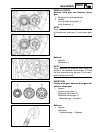
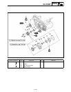
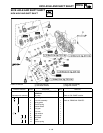
4. Install:
● Lock washer 1
● Nut (balancer) 2
● Primary drive gear 3
● Nut (primary drive gear) 4
NOTE:
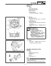
● Install the primary drive gear with its stepped
side b facing the engine.
● Place an aluminum plate a between the
teeth of the balancer drive gear 5 and
driven gear 6.
5. Bend the lock washer tab.
T
R
.
.
50 Nm (5.0 m · kg, 36 ft · lb)
T
R
.
.
75 Nm (7.5 m · kg, 54 ft · lb)
b
3