


4. CONTROL OF VIX DRIVES 61
ES Description
System variable ES controls the required polarity of signal on the enable/shutdown_bar input
(X4 pin 11). The default value of ES is zero (ES=0), therefore to enable the drive connect X4
pin 11 to X4 pin 4 (0V). With ES=1 X4 pin11 may be left open circuit to enable the drive. To
energise the drive, the drive must be enabled and the ON command issued. The function of
this input differs when in mode ‘MP’, please refer to the Command Reference section for
more details.
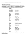
EX Description
System variable EX controls the style and protocol of the drive’s serial communications link.
IP, IT and MV Description
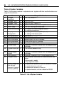
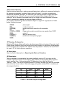
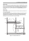
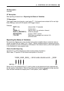
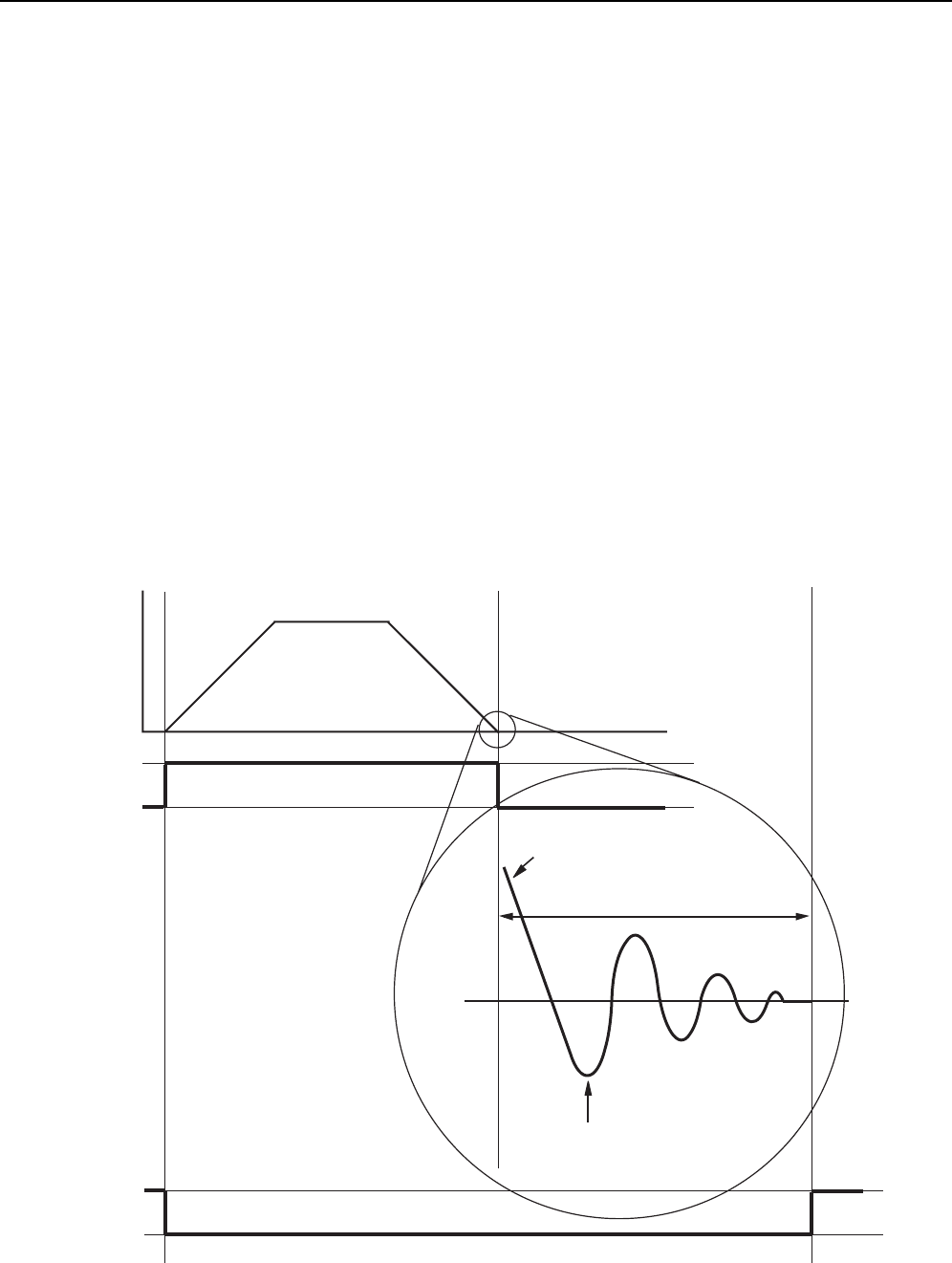
System flag variables IP (In Position) and MV (Moving) together with variable IT (In position
Time) interact with one another as shown in Figure 4-2. The MV flag is only high whilst
commanded motion is taking place. The IP flag can only go high once movement has
stopped and the IT timer value has timed-out. Consequently you need to set IT to a time
long enough to ensure velocity variations (ringing) has ceased.
Velocity
main move
Time, seconds
MV
IT
1
1
0
0
IP
(revs/sec)
0
ERROR
RINGING
APPROACHING
POSITION
Figure 4-2. Interaction of MV, IP, & IT