


36 VIX IM MICROSTEPPER INDEXER DRIVE USER GUIDE
User Inputs
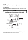
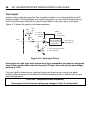
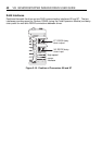
Inputs can be configured using the Easi-V graphic interface or by writing directly to the IC
system variable. By adjusting the user input configuration, you can set the input switching
level threshold and you can set the internal input resistor to be a pull-up or a pull-down.
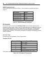
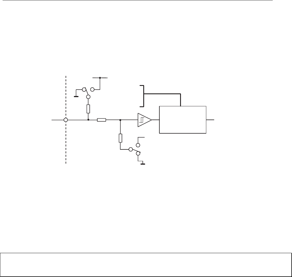
Figure 3-14 shows the position of software switches.
4K7
0V
'1'
'1'
'0'
'0'
'1' = Pull-up
'0' = Pull-down
(default)
'1' = 24V threshold (default)
'0' = 5V threshold
0V
o/c
27K
82K
24V
Input
'1' = invert
'0' = non-invert
SWB
SWC
SWA
Logic level as
reported by IS
Logic inverting
network depending
upon input pull-up
pull-down state
Figure 3-14. User Input Circuit
User inputs are high logic level and low level logic compatible, but must be configured
as pull-down inputs when used with low-level 5V logic, since the pull-up mode always
pulls-up to +24V.
Only one input is shown above, individual inputs can be set-up on a one-to-one basis
allowing different inputs to have different threshold switching levels or different pull-up, pull-
down arrangements.
CAUTION – Unexpected motor movement
De-energise the drive before making any changes to the I/O configuration.