


3. ELECTRICAL INSTALLATION 17
EMC Installation
These EMC installation recommendations are based on the expertise acquired during the
development of compliant applications, which Parker believes are typical of the way, a drive
or drives may be used. Provided you have no special installation requirements or untypical
operating environment requirements, ViX drives will conform to current EMC Directives, as
defined at the front of this user guide.
General Requirements
ViX mounted drives, unless used with an XL-PSU, will require an EMC supply filter to meet
EMC installation compliance requirements. Mount the drive on a conductive panel which is
shared with the EMC filters. If the panel has a paint finish, it will be necessary to remove the
paint in certain areas to ensure filters and drive make a good large-area metal to metal
contact between filter case and panel.
Mount filters close to the drive and keep the supply wiring as short as practical. Attempt to
layout the wiring in a way that minimises cross coupling between filtered and non-filtered
conductors. This means avoiding running wires from the output of a filter close to those
connected to its input. Where you wish to minimise the cross coupling between wires avoid
running them side-by-side one another, if they must cross, cross them at 90° to each other.
Keep wiring supported and close to cabinet metalwork.
Recommended EMC filter types are CORCOM 6FC10 for loads up to 6A and 3VK1 for the
+24V supply up to 3A. Multi-axis systems may require higher current rated filters.
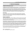
+24V Supply Connections
ViX drives not using an XL-PSU will require a logic supply of +24V DC at 250mA (nominal)
per drive. The +24V powers the controller and I/O circuits. Keeping the +24V independent
of the drive’s internal high voltage bus supply allows the option of keeping the I/O and
controller active when no main supply is present.
Connect the +24V supply to X1 pin7 and the return to X1 pin6, the total wire length, from
supply to drive, must not exceed 10m.
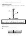
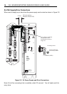
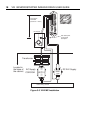
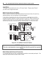
Connect the +24V supply 0V line to system earth (0V) at some convenient point before the
EMC filter input, as shown in the recommended EMC layout diagram, Figure 3-5.
The 24V supply to each drive should be fitted with a time-delay fuse, rated at 3A. Note: The
+24V supply used must meet the voltage requirement specification of +24V DC +10% -15%,
ripple <1V p-p.