


3. ELECTRICAL INSTALLATION 37
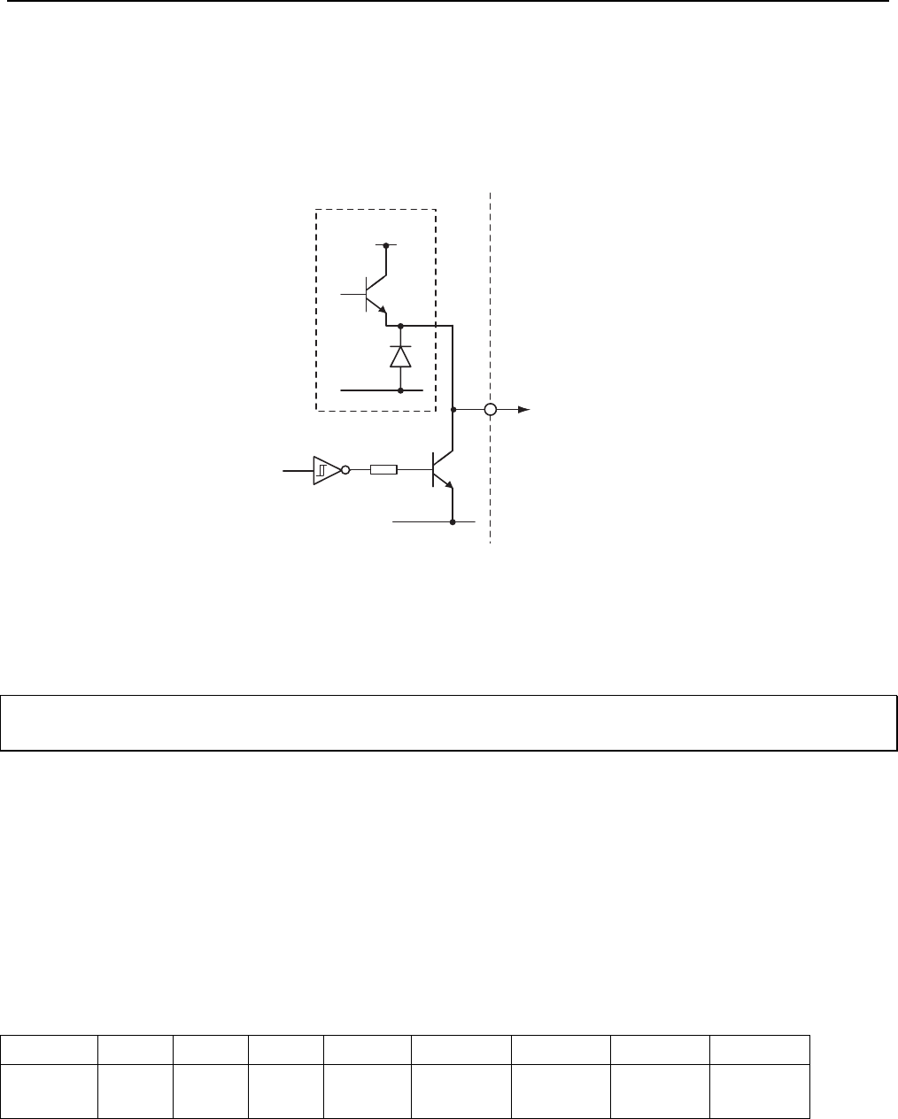
User Outputs
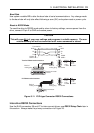
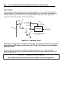
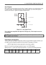
User outputs can be configured using the Easi-V graphic interface or by writing directly to the
IC system variable. By adjusting the user output configuration, you can set the output to
source or sink current. Figure 3-15 shows the output circuit.
+24V
0V
Output
'1' = Current source
'0' = Current sink
Common IC
housing all
top-switches
for all outputs
0V
Figure 3-15. User Output Circuit
User outputs are compatible with high-level 24V logic only. Each output can source
or sink 50mA.
Note: The easiest way of configuring the drive’s inputs and outputs is to use the
Easi-V graphic user interface.
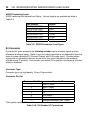
Input/Output Configuration
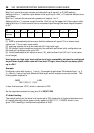
To set-up the input and output configuration without using the EASI-V graphic interface, you
will need to write configuration patterns to the two-byte IC parameter, as shown.
aW(IC,{4 digit decimal number equivalent to a two-byte number})
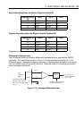
Bits 8 to 12 control the switching threshold of inputs 1 to 5 (SWC setting).
Setting a bit to a ‘1’ gives a 24V switching threshold, a ‘0’ gives a 5V switching threshold.
Bit 15141312 11 10 9 8
IC
content
not
used
not
used
not
used
in_5 in_4 in_3 in_2 in_1