


3. ELECTRICAL INSTALLATION 19
Motor Connections to the Drive
The recommended wire size for ViX250IM/500IM motor cables, of length less than 20m, is
1mm
2
. For motor cable lengths greater than 20m (up to a maximum of 50m) use a wire size
of 2.5mm
2
. Use a cable containing five conductors plus the braided screen (such as Lapp
34805), the green wire being used to provide an earth return to the drive. Termination at the
motor must be made using a 360° bond to the motor body, and this may be achieved by
using a suitable clamp. Many stepper motors are designed to accommodate an appropriate
terminal gland which can be used for this purpose.
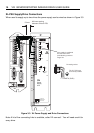
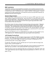
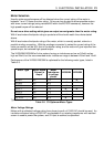
At the drive end of the cable, a 360° connection to the screen should be made using the
P-clip provided beneath the motor connector. The P-clip needs to be firmly clamped to the
copper braid. If the connection appears loose, fold the braid back on itself to increase the
amount of braid under the clip and re-tighten.
Custom cables will require the cable insulation to be removed to expose the braided screen.
If you are using a motor cable with 2.5mm
2
conductors the size of the P-clip will need to be
9mm to accommodate the increased cable diameter. A ferrite absorber, with a specification
matching that of the Chomerics H8FE-1115-NC, is also required to be positioned on the
motor cable using heat shrink sleeving or cable ties. The position of the absorber should be
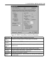
within 150mm of the drive. Always secure the cable using the P-clip, as shown. Do not rely
upon the connector alone holding the motor cable in place. Avoid stress on the X1
connector by hanging cables, as this may lead to connector over-heating.
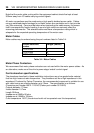
Make a 360° connection to the screen using one of the stainless steel or brass P-clips
supplied within the fit kit.
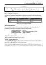
Size Parker part number
9mm ID 4216.101
10.7mm ID 4216.102
12.3mm ID 4216.103
Table 3-3. P Clip sizes
Three different size ‘P’ clips allow the use of a variety of motor power cables from different
manufactures.
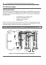
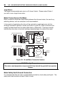
There must be no break in the 360° coverage that the screen provides around the cable
conductors. If a connector must be used it should retain the 360° coverage, possibly by the
use of an additional metallic casing where it passes through the bulkhead of the enclosure.
The cable screen must not be bonded to the cabinet at the point of entry. Its function is to
return high-frequency chopping current back to the drive. This may require mounting the
connector on a sub-panel insulated from the main cabinet, or using a connector having an
internal screen which is insulated from the connector housing. Within the cabinet itself, all
the motor cables should lie in the same trunking as far as possible. They must be kept
separate from any low-level control signal cables. This applies particularly where the control
cables are unscreened and run close to the drive.