


150 VIX IM MICROSTEPPER INDEXER DRIVE USER GUIDE
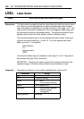
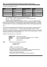
Summary of microstepper modes
Mode Source Enable/Energise Limits
MA TG Enable Local
MB ANA I/P Enable Local
MC TG Enable Local
MI TG Enable Local
MP ENC I/P Energise/Shutdown Remote
Key:
TG – Trajectory Generator (internal command reference)
ANA I/P – ANA1+, ANA1- analogue input on X4. See also AO and AB.
ENC I/P – The encoder inputs on X4
Enable/Energise – describes the function of X4 pin 11. For a ViX indexer drive this
pin is used for the enable function and its active sense is programmed using ES. Disabling
the drive causes a drive fault. In mode position, the drive acts as a base drive (non indexer
mode) and X4 pin 11 can be used to energise/shutdown the drive without generating a drive
fault.
The MP mode provides base drive functionality, that is, step, direction, energise input and
fault output. In this mode, X4 pin 11 is used to energise/de-energise the drive and the
ON/OFF commands are prohibited. Local limits must be disabled by the user and monitored
instead by the system controller providing the step, direction and energise signals, hence the
reference to remote limits in the above table.
Example of step and direction configuration:
1LIMITS(3,0,0) ;do not use local limits
1W(ES,0) ;X4.11 low = energise, high (open circuit) = shutdown
1W(EI,0) ;step and direction input mode
1MP ;mode position
Note
Status bit 25 indicates motion direction:
1=negative, CCW
0=positive, CW
In MA the command H is ignored
You should not use following in mode MA.
Applying a step waveform to the analogue input will cause the velocity to
ramp with acceleration A to avoid stalling the stepper.
Do not use Go Home in MB mode.
Hitting a limit in MB or MC mode gives the same response.