


3. ELECTRICAL INSTALLATION 27
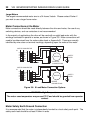
X2
X3
X1
X4
X5
ST
HV FB
24-80V DC +HV
0V / GND -HV
Earth PE
24V DC
10
9
8
7
6
5
4
3
2
1
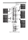
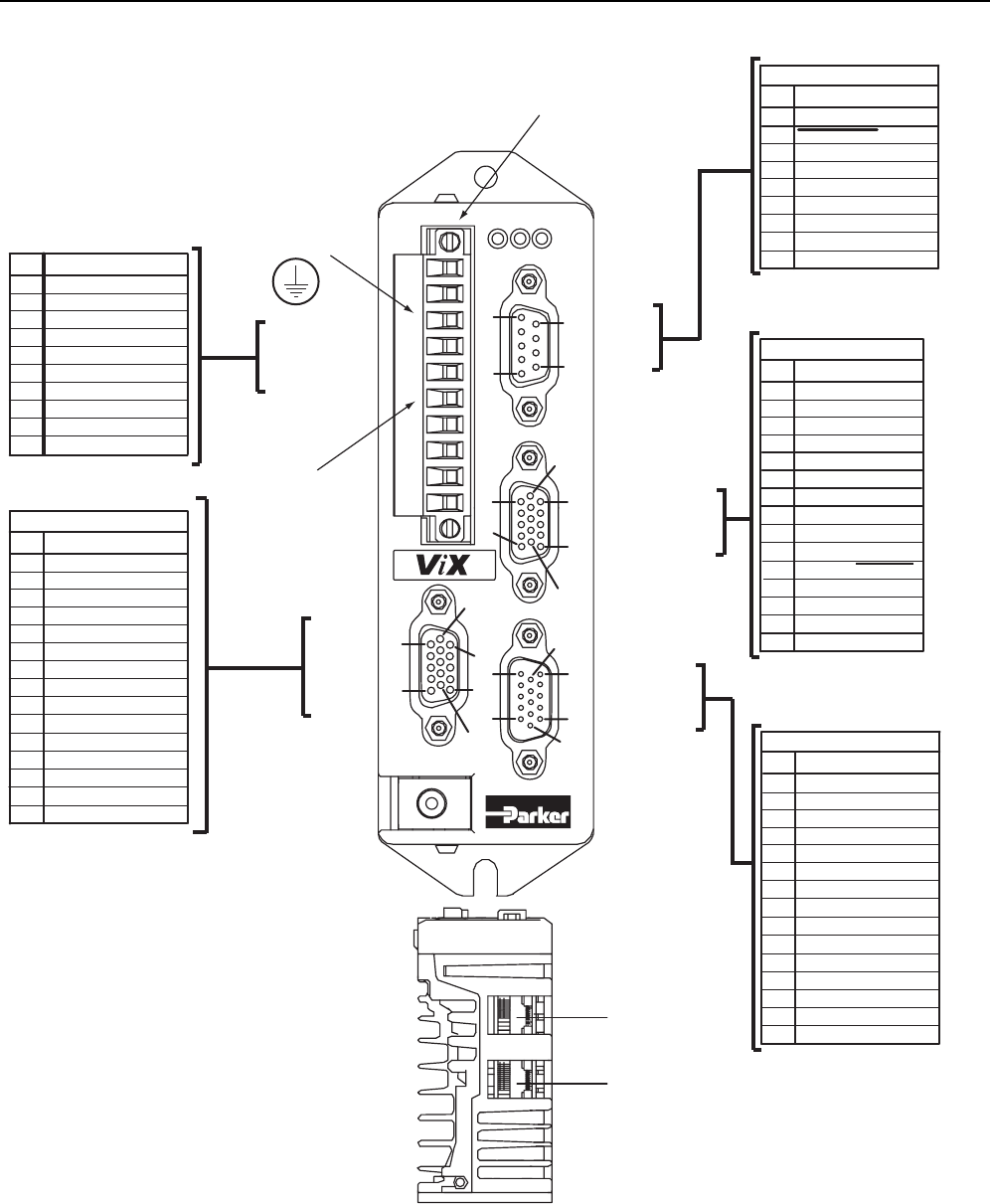
X1
Power & Motor
0V (GND 24v DC)
Motor Gnd
Motor phase (A+)
Motor phase (A-)
Motor phase (B+)
Motor phase (B-)
15
15
10
10
10
10
11
11
9
6
15
11
6
6
6
1
1
1
1
1
5
5
5
5
RS232
9-way
socket
Control/Aux I/O
15-way
socket
User I/O
15-way
plug
Power & motor
10-way
connector
A range of
mating connectors
are supplied, depending
upon the type of fit-kit
ordered.
Feedback enc. Z+
Feedback enc. Z-
GND
Reserved
Reserved
1
2
3
4
5
6
7
8
9
10
11
12
13
14
15
X2
Function
Feedback, Digital encoder
+5V output
GND
Feedback enc. A-
Feedback enc. A+
Feedback enc. B-
Feedback enc. B+
Reserved
Reserved
Reserved
Motor overtemp
Rx+/Tx+ (RS485)*
Drive reset
RS232 GND
RS232 Rx
1
2
3
4
5
6
7
8
9
X3
Function
Communications
RS232 Tx
Rx-/Tx- (RS485)*
RS232 Tx (D loop)
Do not connect
+5V output
*requires CAN option
0V
0V
0V
Output 2
Reserved
1
2
3
4
5
6
7
8
9
10
11
12
13
14
15
X5
Function
User I/O
Output 1
Input 5 (limit+)
Input 4 (limit-)
Input 3 (Home)
+24V
+24V
Input 2 (Reg)
+24V
Output 3
Input 1 (stop)
ANA1+ IN
ANA1- IN
0V
0V
Enc. B+ OUT
1
2
3
4
5
6
7
8
9
10
11
12
13
14
15
X4
Function
Control/Aux I/O
+5V output
Fault output
Enc. A-/Step- IN
Enc. B-/Dir- IN
Energise/Shutdown*
Enc.A+/Step+ IN
Enc. A- OUT
Enc. B+/Dir+ IN
Enc. A+ OUT
Enc. B- OUT
Primary
encoder
15-way
socket
Fixing position
for motor lead
earth clip, included
in fit kit
Motor Earth
ME
Protective Earth
PE
X7 (OUT)
1
8
1
8
RJ45 connectors
X6 (IN)
High speed
comm.
Interface
*Active high/low mode configurable
using system variable ES
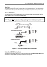
Figure 3-10. ViX Connector Pin Layout