


Adjustment Procedures
Adjustment Procedures
5Ć6
20. Set the READOUT INTENSITY control fully counterclockwise (off).
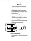
21. Adjust R323 on the Display Driver for the best geometry (minimum
bowing) of the time mark display across the entire graticule area.
22. Set the READOUT INTENSITY control to view the readout.
23. Disconnect the calibration setup from the oscilloscope.
Low Frequency Output Compensation
Equipment Required: One pulse generator (item 10), one precision coaxial
cable (item 5), one 50 W termination (item 3), and one dualĆinput coupler
(item 7).
Adjustment Locations: This procedure requires adjustments to the Display
Driver board. See Figure 5Ć14 on page 5Ć19 for the location of the adjustĆ
ments.
1. Display channel 1, turning all others off.
2. Press the AUTOSET button.
3. Set the volts/div scale to 50 mV.
4. Set the sec/div scale to 1 ms.
5. Press the ALT/CHOP, ADD button and set DISP to Alt.
6. Press the VERTICAL MENU button and set CPLG to AC.
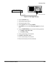
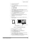
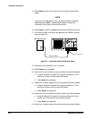
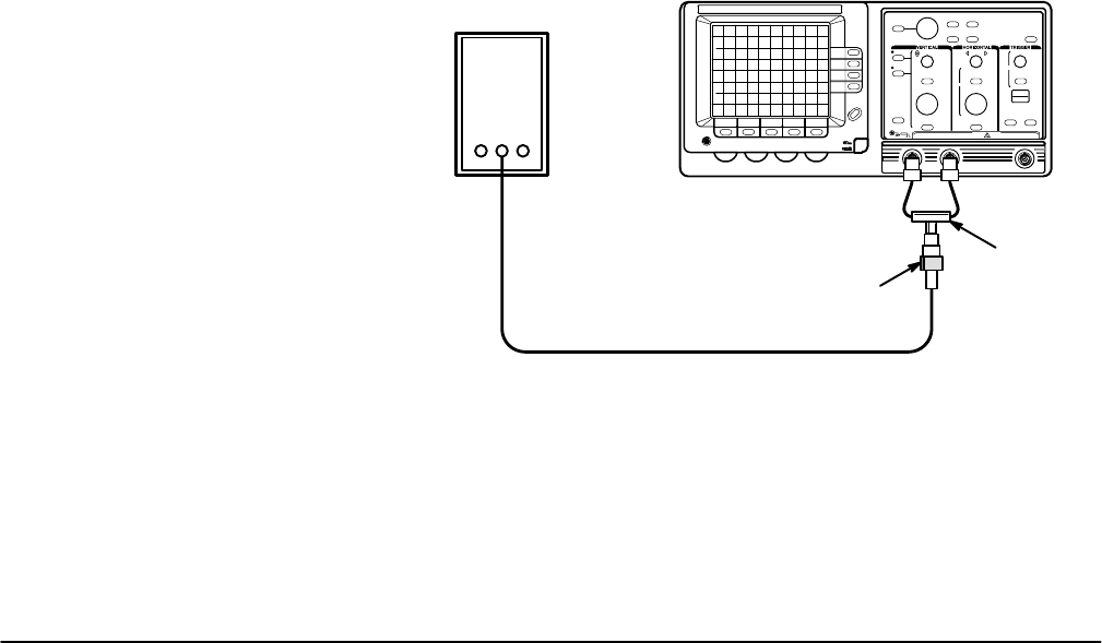
7. Connect the positive fast rise pulse output of the pulse generator to the
CH 1 and CH 2 input connectors as shown in Figure 5Ć3.
Pulse Generator
Precision Cable
50 W Termination
DualĆinput
Coupler
Figure 5Ć3:ăLow Frequency Output Compensation Calibration Setup
8. Set the pulse generator for fast rise period of 1 ms and a 4 division
display.
9. Press the SET LEVEL TO 50% button.