


Removal and Installation Procedures
TAS 455 and TAS 465 Service Manual
6Ć27
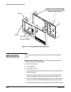
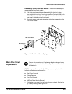
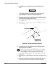
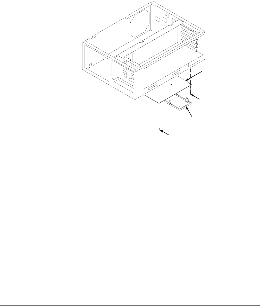
6. Remove the Display Driver board from the chassis, but leave the clear
plastic sheet in place.
7. Replace the Display Driver board by performing the reverse of the
procedure described in steps 1 through 6.
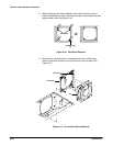
Display Driver
Board (A3)
Mounting Screw
High Voltage Cover
Mounting Screw
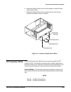
Figure 6Ć14:ăLocation of Display Driver Board
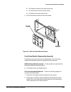
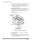
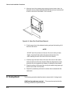
The procedures that follow describe how to remove and install the CRT
Implosion Shield. The method to accomplish this is different depending on
the serial number of your instrument. Choose the correct procedure for your
instrument by comparing your instrument serial number to those listed.
Current MethodĊThe following procedures describe the removal of the
CRT Implosion Shield for the instrument models described in the following
note.
NOTE
TAS 455 Ċ SN: B011876 and Above
TAS 465 Ċ SN: B011640 and Above
CRT Implosion Shield