


Performance Tests
Performance Verification
4Ć20
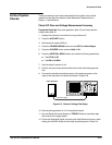
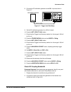
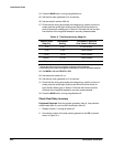
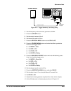
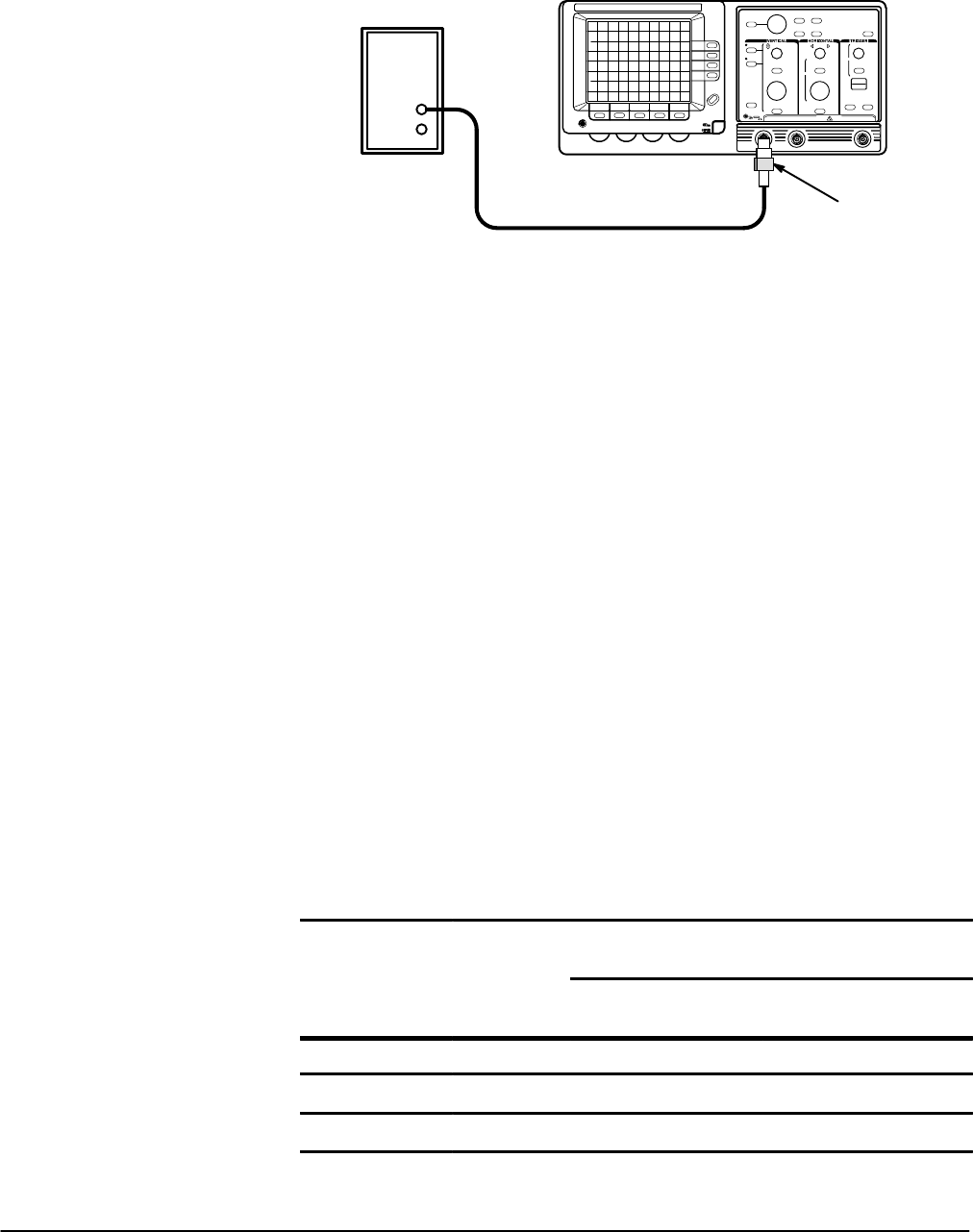
2. Connect the output of the time marker generator to the CH 1 input as
shown in Figure 4Ć10.
Time Mark Generator
50 W Termination
Precision Cable
Figure 4Ć10:ăTiming Test Setup
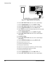
3. Set the output of the generator for 20 ns markers.
4. Press the AUTOSET button.
5. Set the sec/div scale to 20 ns.
6. Set the volts/div scale to 500 mV.
7. Center the time mark display vertically.
8. Press the CURSOR button and set DTIME to On.
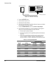
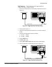
9. Position the rising edge of the second time mark to the second vertical
graticule line.
10. Align the active cursor to the second time mark at the point the rising
edge intersects the center horizontal graticule line using the General
Purpose Knob.
11. Press the TOGGLE button and align the second cursor to the tenth time
mark at the point the rising edge intersects the center horizontal
graticule line using the General Purpose Knob.
12. Check that the TimeĆmark to Graticule Accuracy and the Time Cursor
Readout Accuracy over the center eight divisions are within the limits
shown for each Sec/Div Scale listed in Table 4Ć4.
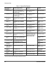
TableĂ4Ć4:ăTime Base and Cursor Accuracies (Mag Off)
TimeĆmark to
Graticule Accuracy
Time Cursor
Readout Accuracy
Sec/Div Scale
(Mag Off)
Time Mark
Setting
Over Center
8 Divisions
2nd and 10th
Time Marks
20 ns 20 ns ±0.16 division 157 ns to 163 ns
50 ns 50 ns ±0.16 division 392 ns to 408 ns
100 ns 0.1 ms ±0.16 division 784 ns to 816 ns