


Removal and Installation Procedures
Maintenance
6Ć38
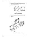
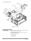
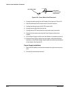
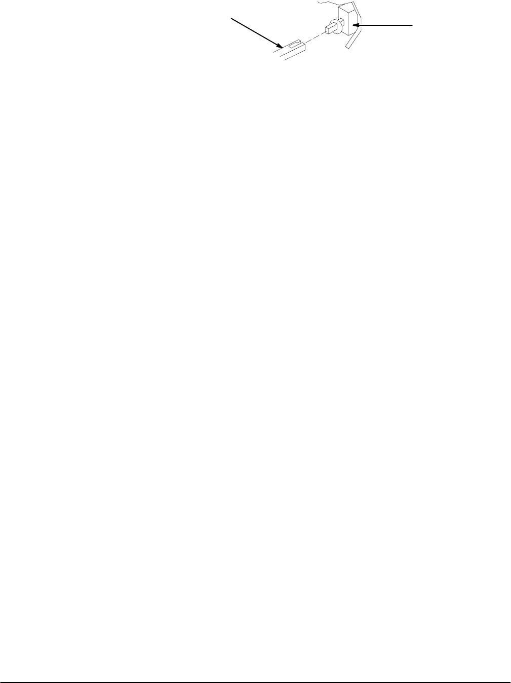
Power Switch
Located on Power
Supply Module
Power ButtonShaft
Figure 6Ć22:ăPower Button Shaft Disconnect
3. Unplug the cables going to the A3 Display Driver board at J70 and J71.
4. Set the oscilloscope so its bottom down on the work surface.
5. Unplug the cable going to the A5 CPU board at J55.
6. Unplug the twoĆwide cable from the fan.
7. Unplug the red CRT anode lead from the power supply connector.
8. Remove the two screws securing the Power Supply module to the
chassis.
9. Lift the Power Supply module out of the chassis to complete its removal.
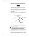
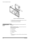
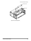
10. Slide the Power Supply module into the chassis, noting that the tab at
the bottom of the Power Supply module slides into the slot at the bottom
of the chassis. See Figure 6Ć23.
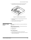
Power Supply Installation
1. Reconnect all cables and wires disconnected during the removal proceĆ
dure.
2. ReĆinstall all components removed.