


Troubleshooting
TAS 455 and TAS 465 Service Manual
6Ć49
No
Yes
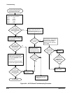
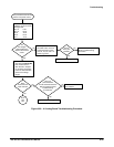
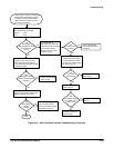
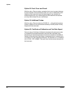
This procedure checks the A62 Front
Panel module. Since the front panel
is difficult to probe while installed,
measurements are taken on J30 of
the processor module.
Measure the power supply voltages
on J30 of the A5 CPU board.
Pin 10 -5.2V
Pin 1 +5.2V
Are
the voltages
approximately the same
as the nominal
value?
No
Yes
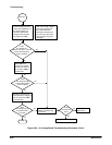
Turn the power off.
Disconnect the cable from
the A62 Front Panel module
to the A5 CPU board.
Check pins 1 and 10 for
shorts to ground.
Yes
No
Are
any of the pins
shorted?
Disconnect the front panel
cable to J84 on the display
control module and check
the J30 pins 1 and 10 again
for shorts to ground.
Perform the A5 CPU
Board Troubleshooting
Procedure.
Yes
No
Are
any of the
pins shorted?
Replace the A3 Display
Driver board.
Replace the A62 Front
Panel module.
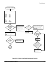
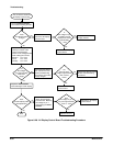
With an oscilloscope, measure the
signals on pins 5 and 6 of J30.
Turn knobs and press buttons
while watching the signals for small
changes in shape.
No
Yes
Does
the signal change
shape with front panel
changes?
Replace the A62 Front
Panel module.
Connect a X10 probe to the CH 1
input connector while watching the
Volts/Div readout on the CRT.
Did
the Volts/Div
readout
change?
Yes
No
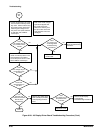
Done.
Measure the voltage on
pinĂ13 of J30 while conĆ
necting and disconnecting
the probe to channel 1.
Did
the voltage change
from about 4.8V to
about 5.2V?
Replace the A62 Front
Panel module
Replace the A1 Analog
board.
Figure 6Ć27:ăA62 Front Panel module Troubleshooting Procedure