


Brief Performance Checks
TAS 455 and TAS 465 Service Manual
4Ć5
8. Press the TOGGLE button and align the active cursor to the bottom of
the signal using the General Purpose Knob.
9. Verify that the DVolts readout is about 5.2 V.
10. Set 1/DT to On.
11. Align the active cursor to a rising edge of the signal using the General
Purpose Knob.
12. Press the TOGGLE button and align the active cursor to the next rising
edge of the signal using the General Purpose Knob.
13. Verify that the 1/DT readout is about 1 kHz.
14. Set DTIME to On.
15. Verify that the DTime readout is about 1 ms.
Verify the Input Channels
1. Display the channel to be verified and turn all others off.
2. Install the probe on the channel to be verified.
3. Press the AUTOSET button.
4. Press the VERTICAL MENU button and set CPLG to DC.
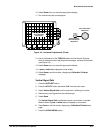
5. Verify that the channel is operational, confirming the following stateĆ
ments are true.
H The vertical scale readout is set to 2 V for the channel under test
and a square wave signal about 2.6 divisions in amplitude is onĆ
screen.
H Pressing the SET LEVEL TO 50% button sets the trigger level
readout to approximately 2.7 V.
H The vertical POSITION control moves the signal up and down the
screen when rotated. Return the bottom portion of the displayed
waveform to the center horizontal graticule line.
H Turning the VOLTS/DIV control counterclockwise and clockwise
decreases and increases the amplitude of the waveform. Return the
volts/div scale to 2 V.
6. Press the VERTICAL MENU button and select CPLG. Select the followĆ
ing coupling types and verify the display.
H Select DC coupling and verify that the waveform amplitude is posiĆ
tiveĆgoing from the center horizontal graticule line.
H Select AC coupling, press the SET LEVEL TO 50% button, and
verify that the waveform is centered at about the center horizontal
graticule line.
H Select GND coupling and verify that a straight line is displayed (no
waveform).