


Adjustment Procedures
TAS 455 and TAS 465 Service Manual
5Ć7
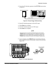
10. Press the CURSOR button and set DVOLT to On.
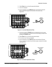
11. Set the cursors 5 divisions apart using the General Purpose Knob and
the TOGGLE button.
12. Set the volts/div scale to 20 mV.
13. Press the CH 2 button.
14. Set the channel 2 volts/div scale to 20 mV.
15. Press the VERTICAL MENU button and make the following selections
from the menu (channel 2):
H Set CPLG to GND
H Set VAR to Off
H Set INV to Off
H Set BW to Full
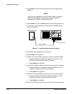
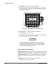
16. Position the channel 2 trace to the center vertical graticule line.
17. Set CPLG to AC.
18. Adjust R111 located on the Display Driver board for minimum vertical
movement of the readout (over the entire graticule area).
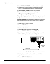
19. Disconnect the test setup from the oscilloscope.
Factory Horizontal Cal
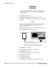
Equipment Required: One time mark generator (item 9), one precision
coaxial cable (item 5), and one 50 W termination (item 3).
Prerequisites: CRT adjustment procedure.
NOTE
To enable factory calibration on oscilloscopes with firmware version
2.10 or above, remove jumper J205 (CAL-DIS) on the CPU board.
(See Figure 5Ć17 on page 5Ć22 for the location of J205.) If you do
not remove this jumper, the message See manual to enable FactoĆ
ry Cal" appears when you select the factory calibration routine.
Firmware versions below
2.10 do not have the calibration lockout
feature and the factory calibration routine can still execute with J205
installed.
1. Disconnect all signal inputs from the oscilloscope.
2. Press the UTILITY button to display the Utility menu.