


Performance Tests
TAS 455 and TAS 465 Service Manual
4Ć15
These procedures check those characteristics that relate to the vertical
system and are listed as checked under Warranted Characteristics in
Section 1, Specifications.
Check DC Gain and Voltage Measurement Accuracy
Equipment Required: One pulse generator (item 10) and one precision
coaxial cable (item 5).
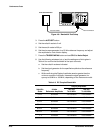
1. Display the channel to be verified, turning all others off.
2. Press the AUTOSET button.
3. Set the sec/div scale to 500 ms.
4. Press the TRIGGER MENU button and set CPLG to Noise Reject.
5. Press the CURSOR button and set DVolt to On.
6. Press the VERTICAL MENU button and make the following selections:
H Set CPLG to DC
H Set BW to 20 MHz
7. Set the volts/div scale to 2 mV.
8. Position the trace three divisions below the center horizontal graticule
line.
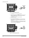
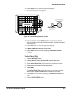
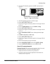
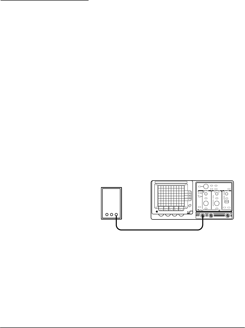
9. Connect the standard amplitude output of the pulse generator to the
input of the channel to be verified as shown in Figure 4Ć6.
Pulse Generator
Precision Cable
Figure 4Ć6:ăGain and Voltage Test Setup
10. Set the pulse generator for 10 mV amplitude output.
11. Use the General Purpose Knob and TOGGLE button to precisely align
the cursors to the signal peaks.
12. Check the Displayed Signal Accuracy and Volts Readout Accuracy while
setting the Volts/Div Scale and the Input Amplitude given in Table 4Ć2.
Vertical System
Checks