


Troubleshooting
Maintenance
6Ć48
Part
Two
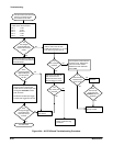
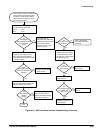
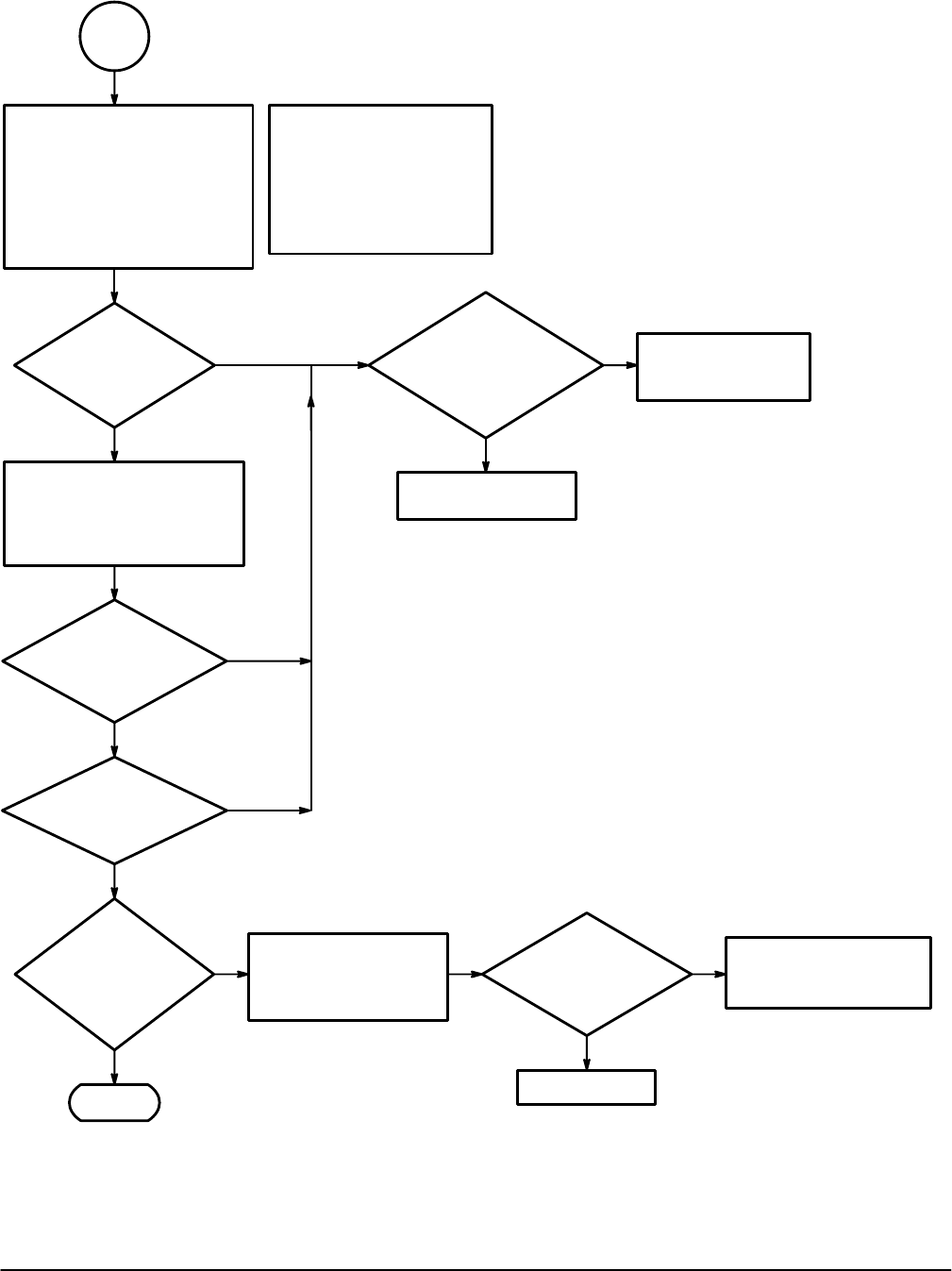
Done.
No
Yes
Does
the voltage vary as
the position knob is
moved?
Have
you perform the
A1 Analog Board
Troubleshooting
Procedure?
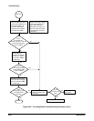
Press the CH1 button and
rotate the vertical position knob
while measuring the voltage
across the pins 16 and 17 of J67
with a DMM or oscilloscope.
No
Yes
Does
the voltage vary as
the position knob
is moved?
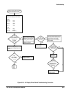
Measure the voltage at the
base (middle pin) of Q361
while adjusting the focus
knob.
No
Yes
Can
the trace and
readout be focused
with the focus
thumbwheel?
No
Yes
Does
the voltage vary as
the position knob
is moved?
Perform the A2 Display
Control Board
Troubleshooting Procedure.
Replace the CRT.
No
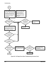
Replace the A3 Display
Driver board.
Perform the A1 Analog
Board Troubleshooting
Procedure.
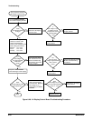
Are
traces and
readout visible on
the CRT?
Yes
No
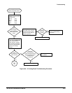
Put the oscilloscope in XY mode.
Turn the readout intensity all the
way down. Select CH2 and vary
the vertical position knob while
measuring the voltage across
J75 pins 3 and 1 (W76 and W75
on TAS 485) with a DMM or
oscilloscope.
Note: In XY mode, a single
spot should appear near
the center of the CRT.
Reduce the intensity until
the spot is dim so that the
CRT phosphor will not be
damaged.
Yes
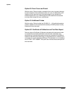
Figure 6Ć26:ăA3 Display Driver Board Troubleshooting Procedure (Cont.)