


Removal and Installation Procedures
Maintenance
6Ć26
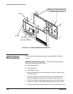
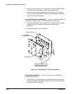
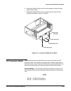
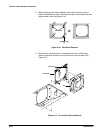
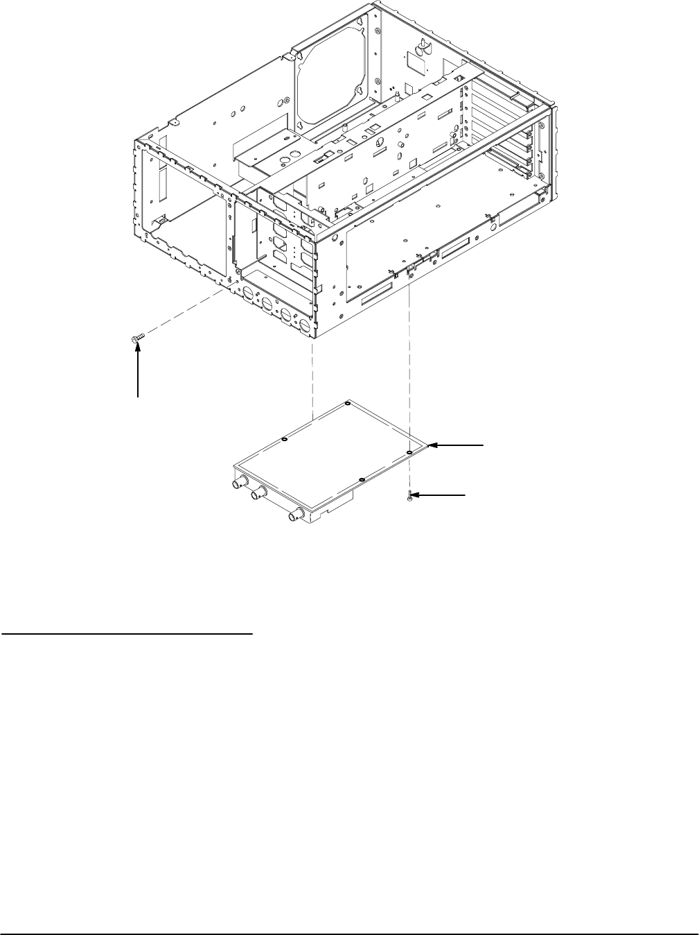
Mounting Screws (4)
A1 Analog board
Mounting Screws (4)
Figure 6Ć13:ăA1 Analog Board Removal
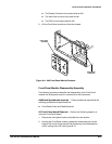
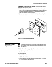
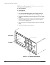
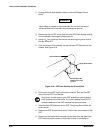
Remove and replace the Display Driver board as follows:
1. Remove the plastic high voltage cover from the rear of the Display Driver
board (A3). Refer to FigureĂ6Ć14.
2. Disconnect the delay line from its holder and at connector J69 on the
Display Driver board.
3. Disconnect the cables from J70, J71, J72, J73, J74, J75, and J80 on the
Display Driver board.
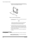
4. Disconnect J67 from the Analog Board (A1).
5. Remove the four TĆ15 Torx screws used to attach the Display Driver
board to the chassis.
Display Driver Board
(A3)