


TAS 455 and TAS 465 Service Manual
9Ć1
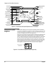
Diagrams and Circuit Board Illustrations
This section contains circuit board illustrations, component locator tables,
waveform illustrations, and schematic diagrams for this oscilloscope.
Graphic symbols and class designation letters are based on ANSI Standard
Y32.2Ć1975. Abbreviations are based on ANSI Y1.1Ć1972.
Logic symbology is based on ANSI/IEEE Std 91Ć1984 in terms of positive
logic. Logic symbols depict the logic function performed and can differ from
the manufacturer data.
The tilde (~) preceding a signal name indicates that the signal performs its
intended function when in the low state.
Other standards used in the preparation of diagrams by Tektronix. Inc are:
H Tektronix Standard 062Ć2476 Symbols and Practices for Schematic
Drafting
H ANSI Y14.159Ć1971 Interconnection Diagrams
H ANSI Y32.16Ć1975 Reference Designations for Electronic Equipment
H MILĆHDBKĆ63038Ć1A Military Standard Technical Manual Writing HandĆ
book
Electrical components shown on the diagrams are in the following units
unless noted otherwise:
Capacitors: Values one or greater are in picofarads (pF). Values less
than one are in microfarads (mF).
Resistors: Values are in Ohms (W).
Each assembly in the instrument is assigned an assembly identifier (for
example, MAIN or A5). The assembly identifier appears on the circuit board
outline on the diagram (see Figure 9Ć1), in the title for the circuit board
component location illustration, and in the lookup table for the schematic
diagram and corresponding component locator illustration. The Replaceable
Electrical Parts list is arranged by assemblies in numerical sequence; the
components are listed by component number.
Symbols
Component Values
Graphic Items and
Special Symbols
Used in This Manual