


Diagrams and Circuit Board Illustrations
Diagrams
9Ć2
Locator Grid
Function Block
Title
Board Outline
Internal Screw
Adjustment
Onboard Jumper
Digital Ground
Refer to Assembly
& Diagram Number
Off board
Connector
Active Low
Signal
Signal From
Another Diagram,
Same Board
Assembly Number
& Board Name
Power Termination
Strap
Panel
Control
Male Coaxial
Connector
Female Coaxial
Connector
Heat Sink
Decoupled
Voltage
Diagram Number
Diagram Name
SYN GENERATOR A5
Component on
back of board
Assembly Number
Refer to Waveform
Assembly Number
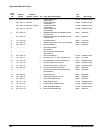
Figure 9Ć1:ăGraphic Items and Special Symbols Used in This Manual
The schematic diagram and circuit board component location illustrations
have grids. A lookup table is provided for ease of locating a component. The
circuit board illustration only appears once; its lookup table lists the diagram
number of all diagrams that the circuitry appears on.
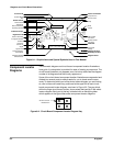
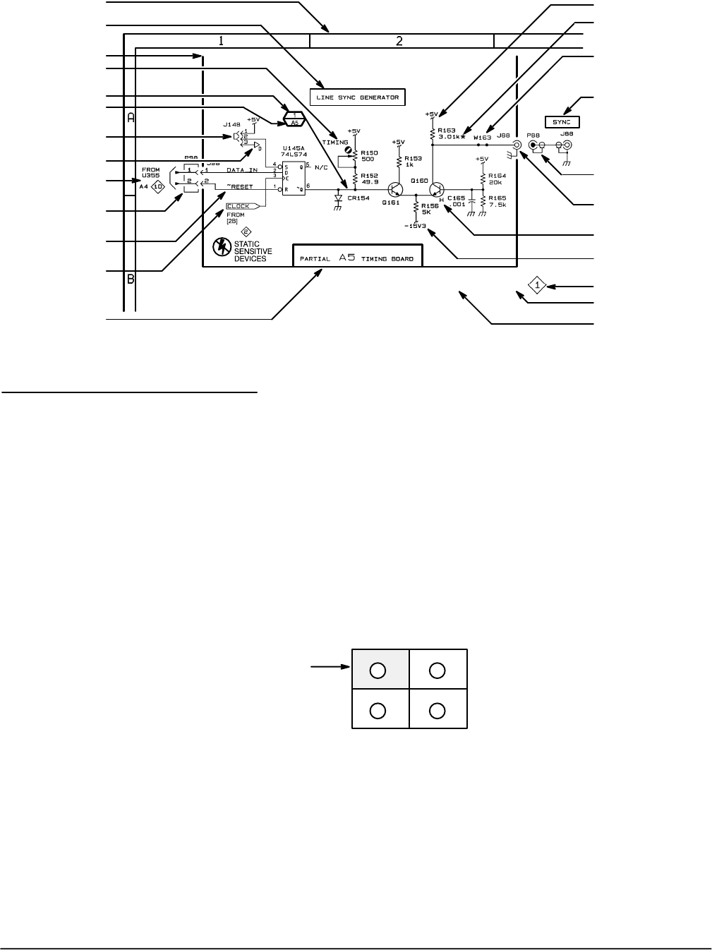
Some of the circuit board component location illustrations are expanded and
divided into several parts to make it easier for you to locate small compoĆ
nents. To determine which part of the whole locator diagram you are looking
at, refer to the small locator key positioned at the upper left of each circuit
board component locator diagram, as shown in Figure 9Ć2. The gray block,
within the larger circuit board outline, shows where that part fits in the whole
locator diagram. Each part in the key is labeled with an identifying letter
which appears in the figure titles under component locator diagrams.
A B
DC
Section of Circuit
Board Shown
Figure 9Ć2:ăCircuit Board Component Locator Diagram Key
Component Locator
Diagrams