


Adjustment Procedures
TAS 455 and TAS 465 Service Manual
5Ć15
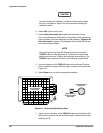
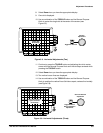
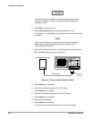
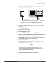
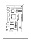
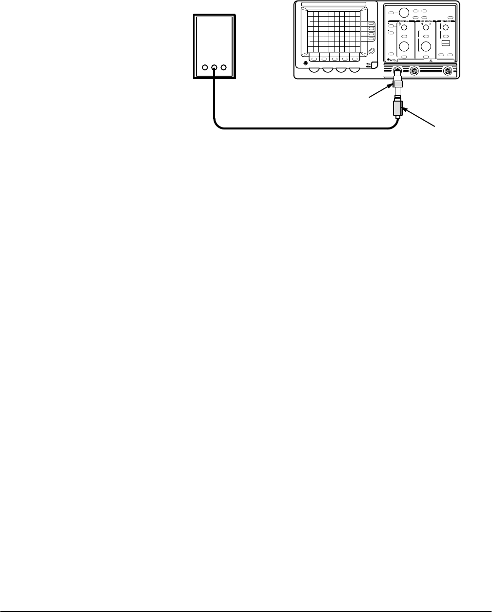
2. Connect the positive fast rise pulse output of the pulse generator to the
CH 1 input as shown in Figure 5Ć12.
Pulse Generator
50 W Termination
Precision Cable
5X Attenuator
Figure 5Ć12:ăHigh Frequency Step Response Test Setup
3. Set the pulse generator fast rise period to 1 ms and pulse amplitude to
midĆrange.
4. Press the AUTOSET button.
5. Set the volts/div scale to 10 mV.
6. Set the sec/div scale to 200 ns.
7. Press the VERTICAL MENU button and set CPLG to DC.
8. Adjust the vertical POSITION control and the generator pulse amplitude
to obtain a 5 division, vertically centered, display.
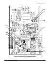
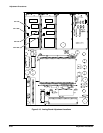
9. TAS 465 Only Ċ Adjust R141 and C122 on the Display Driver board for
flattest long term response of the pulse front corner.
10. Set the sec/div scale to 20 ns.
11. Adjust R140 and C121 on the Display Driver board for minimum signal
aberrations of the pulse front corner.
NOTE
Some interaction of the adjustments made in steps 9 and 11 may
occur. For optimum oscilloscope performance, these steps should
be rechecked after making adjustments.
12. Disconnect the calibration setup from the oscilloscope.