


Removal and Installation Procedures
Maintenance
6Ć32
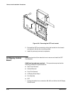
2. Unplug the the 2Ćwide red/black cable from the A2 Display Control
board.
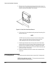
WARNING
HighĆvoltage is present on the anode lead. Do not touch the end of
the anode lead until it has been fully discharged to ground.
3. Disconnect the red CRT anode lead from the A63 Power Supply module
and immediately discharge to chassis ground.
4. Using a
5
@
16
inch nut driver, remove the nut securing the ground wire at
the rear of the CRT.
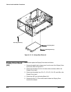
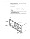
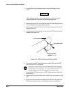
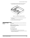
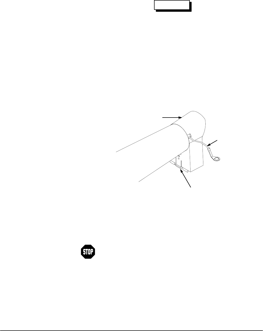
5. From the bottom of the chassis, unsnap the Rear CRT Bracket from the
chassis. See Figure 6Ć18.
Rear CRT Bracket
Release Rear CRT
Bracket Latch From
Chassis
Spring Ground Wire
Figure 6Ć18:ăCRT Rear Bracket and Ground Wire
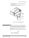
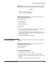
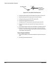
6. Lift the rear of the CRT until it is above the chassis. Then pull the CRT
away from the CRT Front Bracket.
Stop here if you are removing the CRT assembly to gain access to
other portions of the instrument. If you are installing a new CRT or
hardware attached to the CRT, continue with this procedure.
7. Slide the Rear CRT Bracket from the CRT. The Spring Ground Wire will
slide out also.
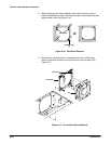
8. Remove the CRT Socket with its cover from the rear pin connector of the
CRT.
9. Disconnect the vertical and horizontal control wires from the side of the
CRT. Note the proper location of both sets of wires for reinstallation.