


TAS 455 and TAS 465 Service Manual
3Ć1
Circuit Description
This section describes the electrical operation of the Tektronix TAS 455 and
TAS 465 Analog Oscilloscopes. Refer to the schematics in the Diagrams
section as necessary.
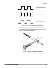
This manual refers to digital logic circuits with standard logic symbols and
terms. Unless otherwise stated, all logic functions are described using the
positive logic convention: the more positive of the two logic levels is the high
(1) state and the more negative level is the low (0) state. Signal states may
also be described as true" meaning their active state or false" meaning
their nonĆactive state. The specific voltages that constitute a high or low
state vary among the electronic devices.
ActiveĆlow signals are indicated by a tilde (~) prefixed to the signal name
(~RESET). Signal names are considered to be either activeĆhigh, activeĆlow,
or to have both activeĆhigh and activeĆlow states.
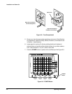
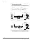
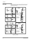
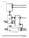
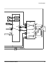
Figure 3Ć1 shows the interconnection paths between the modules of the
TAS 455 and TAS 465 Oscilloscopes.
Logic Conventions
Module
Interconnection