Removal and Installation Procedures
TAS 455 and TAS 465 Service Manual
6Ć21
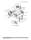
H The Display ControlĆtoĆfrontĆpanel cable at J84
H The menu flex circuitĆtoĆfront panel at J40
H The CPUĆtoĆfrontĆpanel cable at J30
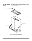
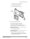
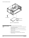
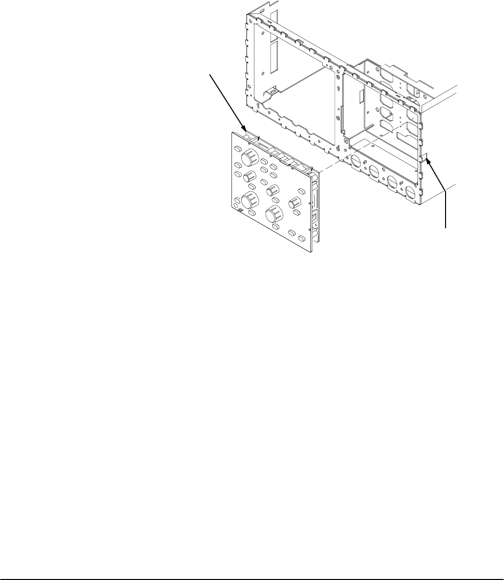
5. Lift the Front Panel module out from the chassis.
Front Panel
Assembly
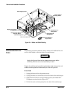
Press Latch
to Release
Figure 6Ć9:ăA62 Front Panel Module Removal
FrontĆPanel Module Disassembly/Assembly
The following procedures describe the disassembly of the Front Panel
module into its subparts once it is removed from the instrument.
Additional procedures required Ċ These procedures require that the
following procedures be performed first:
H FrontĆPanel Knobs and Shafts Removal
A4 Front Panel board Removal Ċ Perform the following steps to reĆ
move the Front Panel board.
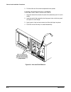
1. Remove the frontĆpanel knobs and shafts from the module.
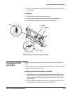
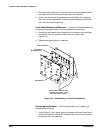
2. Holding the Front Panel module, release the three snap locks at the
edge of the circuit board, then tilt the board away from the assembly
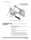
until it unplugs from J35. See Figure 6Ć10.


