


Circuit Description
Theory of Operation
3Ć4
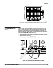
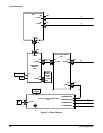
A signal enters the oscilloscope through a probe connected to a BNC on the
A1 Analog board.
Attenuators A1
2
The attenuator hybrids, AT401 and AT402, and the vertical preamplifier IC
select the input coupling, attenuation factor, variable gain, and the invert
function. The processor system controls and calibrates the attenuators.
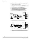
Probe Coding Interface A1
2 3
Probe coding interface signals pass through the A1 Analog board to the A5
CPU board and then to the A4 Front Panel board. The probe interface
signals are digitized on the Front Panel board and communicated to the
processor system to control the instrument.
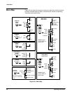
Analog Acquisition Hybrid A1
3
The input signals are routed to the highly integrated analog acquisition
hybrid, U405, which does the analog processing required to provide vertical,
horizontal, and ZĆaxis signals to the A3 Display Driver board. Under control
of the processor, the hybrid provides vertical signal processing, triggers,
sweeps, sequencing logic, and intensity control.
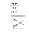
External Trigger A1
1
A high impedance buffer is used to interface the external trigger signal to the
analog acquisition hybrid.
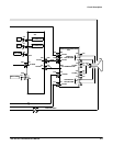
The processor board is a microcontroller design. Microcontroller U201 is the
core of the circuit, operating at 16 MHz. The primary function of the procesĆ
sor is to receive input from the front panel, display the readout, and control
the A1 Analog board.
The processor board can be divided into five subsystems: the processor, the
ROM/RAM, the readout, the frontĆpanel interface, and the analog board
interface. A description of each subsystem follows.
Processor Subsystem A5
1
The processor subsystem consists of a 32Ćbit integrated microcontroller and
its supporting circuits. It contains four peripheral modules; the CPU, a generĆ
alĆpurpose timer (GPT), a queued serial module (QSM), and a system inĆ
tegration module (SIM).
Analog Board
Processor System