


Removal and Installation Procedures
TAS 455 and TAS 465 Service Manual
6Ć29
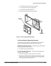
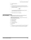
Early MethodĊThe following procedures describe the removal of the CRT
Implosion Shield for the instrument models described in the following note.
NOTE
TAS 455 Ċ SN: B011875 and Below
TAS 465 Ċ SN: B011639 and Below
Additional procedures required Ċ This procedure requires that the
following procedures be performed first:
H Rear Cover Removal
H Cabinet Removal
H Front Trim Removal
H A3 Display Driver Board
H Fan Assembly
H CRT
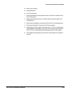
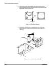
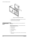
1. From the front of the Implosion Shield, push the top of the shield until it
pops out of the back side of the CRT Front Bracket.
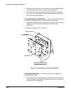
2. ReĆinstall the CRT Implosion shield by snapping the shield into the rear
of the CRT Front Bracket. If installing a new Implosion Shield, remove
the clear protective covers.
3. Install all previously removed components.
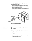
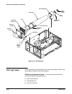
The procedures that follow describe how to remove and install the Fan and
Fan Mount.
Additional procedures required Ċ This procedure requires that the
following procedures be performed first:
H Rear Cover Removal
H Cabinet Removal
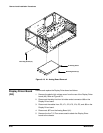
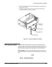
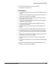
Fan and Fan Mount Removal
1. Set the oscilloscope so its bottom is down.
2. Unplug the fan power cable from the A63 Power Supply module.
3. Rotate the oscilloscope so the side that houses the fan mount is facing
upwards.
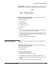
4. Depress the two flex locks to release them (see Figure 6Ć17).
Fan and Fan Mount