


Performance Tests
Performance Verification
4Ć16
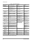
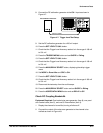
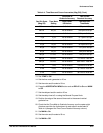
TableĂ4Ć2:ăDC Gain and Delta Volts Accuracy
Volts/Div
Scale
Input
Amplitude
Displayed
Signal Accuracy
Delta Volts
Readout Accuracy
2mV 10 mV 4.87 to 5.13 div 9.80 mV to 10.2 mV
5mV 20 mV 3.9 to 4.1 div 19.6 mV to 20.4 mV
10 mV 50 mV 4.87 to 5.13 div 49.0 mV to 51.0 mV
20 mV 0.1 V 4.87 to 5.13 div 98.0 mV to 102 mV
50 mV 0.2 V 3.9 to 4.1 div 196 mV to 204 mV
100 mV 0.5 V 4.87 to 5.13 div 490 mV to 510 mV
1V 5V 4.87 to 5.13 div 4.90 V to 5.10 V
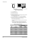
13. Return the volts/div scale to 2 mV and set the pulse generator for 10 mV
amplitude output.
14. Press the VERTICAL MENU button and set VAR to On.
15. Check that rotating the General Purpose Knob counterclockwise reĆ
duces the displayed signal amplitude to two divisions or less. Set VAR
to Off.
16. Disconnect the test setup from the oscilloscope.
17. Repeat this procedure until you have verified all input channels.
18. Press the CURSOR button and set DVolt to Off.
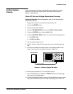
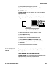
Check Trigger Level Accuracy
Equipment Required: One DC calibration generator (item 11) and one
precision coaxial cable (item 5).
1. Display channel 1, turning all others off.
2. Press the AUTOSET button.
3. Set the sec/div scale to 500 ms.
4. Press the TRIGGER MENU button and make the following selections:
H Set CPLG to DC
H Set SLOPE to Rising
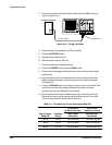
5. Press the VERTICAL MENU button and make the following selections:
H Set CPLG to DC
H Set BW to 20 MHz
6. Set the volts/div scale to 50 mV.
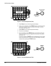
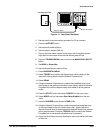
7. Position the trace three divisions below the center horizontal graticule
line.