


Adjustment Procedures
Adjustment Procedures
5Ć4
TableĂ5Ć1:ăAdjustments and Dependencies (Cont.)
Adjustment Prior Completion Requirements
Vertical Gain Adjustment Low Frequency Output CompensaĆ
tion, Factory Vertical Cal, and AttenuĆ
ator Compensation
The following instructions will guide you through each of the adjustments
outlined in Complete Adjustments. Each adjustment section lists all necesĆ
sary equipment required to perform the adjustments.
Power Supply Adjustment
(New Style Power Supply)
This procedure is provided to support instruments with the newer power
supply. No adjustment is necessary with older power supplies. Refer to
pageĂ3Ć8 for details.
Equipment Required: One digital multimeter (item 13) and one adjustment
tool (item 15).
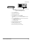
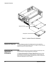
Adjustment Locations: This procedure requires adjustment to the Power
Supply board. See Figure 5Ć16 on page 5Ć21 for the location of the adjustĆ
ment.
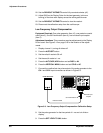
1. Connect the digital voltmeter low lead to chassis ground and connect
the volts lead to the -8.6 V supply (W55-2) on the CPU board.
2. Measure the -8.6 V supply. If the supply measures from -8.56 V to
-8.64 V, the supply is adjusted properly and you may disconnect the
voltmeter.
3. If the power supply is not within the limits specified in step 2, adjust the
-8.6 V ADJ potentiometer (R43) for a voltmeter reading of -8.60 V.
4. Disconnect the voltmeter from the instrument.
CRT Adjustments
Equipment Required: One time marker generator (item 9), one precision
coaxial cable (item 5), and one 50 W termination (item 3).
Adjustment Locations: This procedure requires adjustments to the Display
Driver board. See Figure 5Ć14 on page 5Ć19 for the location of the adjustĆ
ments.
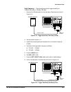
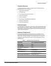
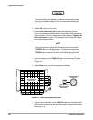
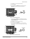
1. Disconnect all signal inputs from the oscilloscope.
2. Display channel 1, turning all others off.
3. Press the AUTOSET button.
Adjustment
Instructions