


Adjustment Procedures
Adjustment Procedures
5Ć14
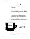
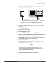
18. Select Done when you have the appropriate display.
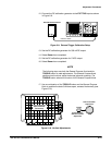
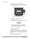
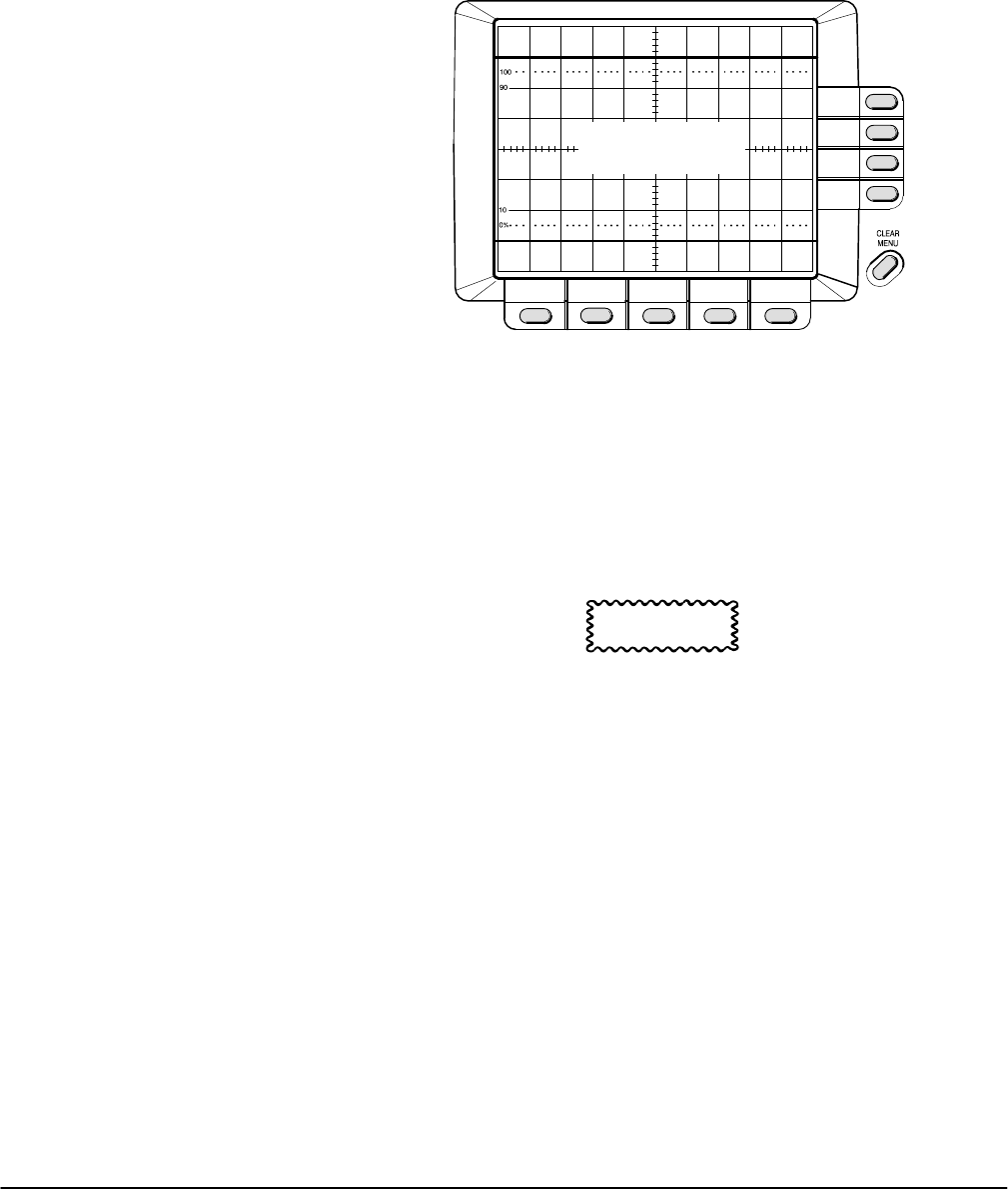
19. Adjust R112 (vertical gain) and R154 (vertical centering) on the Display
Driver board, setting the horizontal cursors 6 divisions apart, centered
vertically (see Figure 5Ć11).
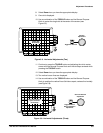
Lines Six Divisions
Apart, Centered
Vertically
Figure 5Ć11:ăAdjusting Vertical Gain and Centering
20. Select Done when you have completed the adjustments.
21. Select Done again to exit the routine.
22. Replace J205 (CAL-DIS) to lock out the calibration routine. (This jumper
only works with firmware version
2.10 and above.)
CAUTION
To prevent accidental loss of calibration, be sure the calibration
lockout jumper (J205) is in place. If J205 is not in place, erroneous
calibration constants can result if the calibration routine is accidenĆ
tally invoked and not properly completed.
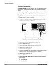
High Frequency Step Response
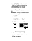
Equipment Required: One pulse generator (item 10), one precision coaxial
cable (item 5), one 5X attenuator (item 1), and one 50 W termination (item 3).
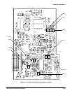
Adjustment Locations: This procedure requires adjustments to the Display
Driver board. See Figure 5Ć14 on page 5Ć19 for the location of the adjustĆ
ments.
Prerequisites: Factory Vertical Cal adjustment procedure.
1. Display channel 1, turning all others off.