


Troubleshooting
Maintenance
6Ć44
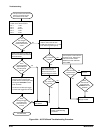
This procedure assumes that
there is front panel control
and readout on the CRT.
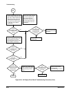
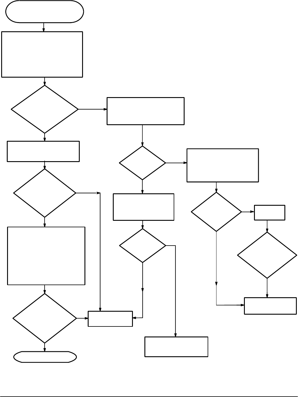
Measure the power supply voltages
at J55 on the A5 CPU board.
Pin 1 -5.2V
Pin 2 +5.2V
Pin 3 Ground
Pin 4 -8.6V
Pin 5 +8.6V
Are
the voltages
approximately the
same as the nominal
value?
No
Yes
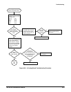
Turn the power off. Remove the
cable to J55 on the A5 CPU
board and check pins 1, 2, 4, and
5 for shorts to ground (pin 3).
Yes
No
Are
any of the pins
shorted?
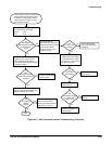
Disconnect the cable at
J30 on the A4 Front
Panel board and check
the pins again for shorts.
Yes
No
Are
any of the pins
shorted?
Perform the A4 Front Panel
board troubleshooting
procedure.
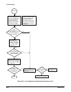
Measure the signal on U217 pin
26 on the A5 CPU board with the
test oscilloscope.
Is the
signal amplitude
approximately 5V
and the period
60 nS?
No
Yes
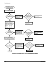
Measure the signal on pins 24
and 25 of J50 on the A5 CPU
board with the oscilloscope while
turning the VOLTS/DIV control
back and forth.
Set the test oscilloscope trigger
to Norm and trigger level to 2.5V.
Does
the signal trigger
the oscilloscope
when the knob is
turned?
No
Yes
Replace the A5
CPU board.
A5 CPU board.
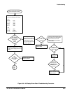
Turn the power off and remove
the power cord. Remove the
fuse from the fuse holder.
Measure the fuse resistance
with a DMM.
No
Yes
Is
the line fuse
resistance less
than 10 W?
Replace the
line fuse.
Replace the A63 Power
Supply module.
Does
the line fuse
blow when the
POWER button is
pressed?
Yes
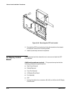
Figure 6Ć24:ăA5 CPU Board Troubleshooting Procedure