


Performance Tests
Performance Verification
4Ć18
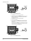
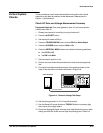
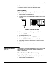
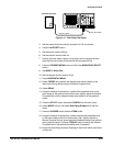
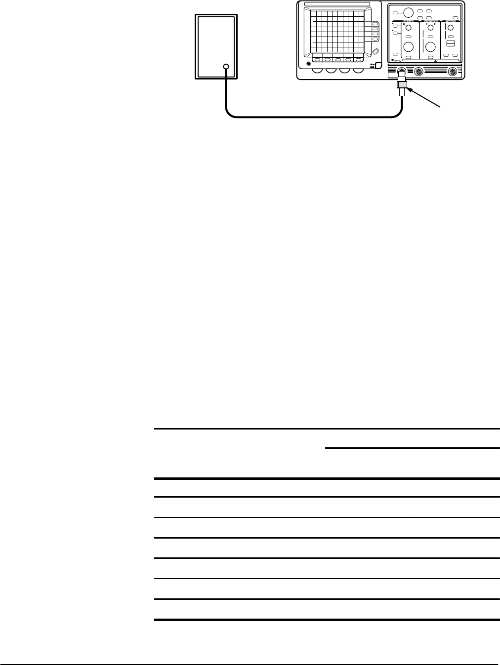
Sine Wave Generator
Precision Cable 50 W Termination
Figure 4Ć8:ăBandwidth Test Setup
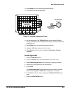
3. Press the AUTOSET button.
4. Set the volts/div scale to 2 mV.
5. Set the sec/div scale to 200 ms.
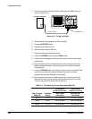
6. Set the sine wave generator for a 50 kHz reference frequency and adjust
the amplitude for a six division display.
7. Press the TRIGGER MENU button and set CPLG to Noise Reject.
8. Use the following substeps (a to c) and the settings and limits given in
Table 4Ć3 to confirm the bandwidth of the input channels.
a. Set the volts/div scale as indicated.
b. Set the signal generator for the specified amplitude at the reference
frequency.
c. While confirming the Display Amplitude remains greater than the
minimum number of divisions, increase the signal generator freĆ
quency to 60 MHz or 100 MHz, depending on the instrument model.
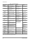
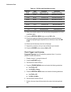
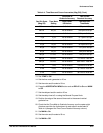
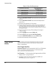
TableĂ4Ć3:ăDC Coupled Bandwidth
Display Amplitude
Volts/Div
Scale
50 kHz
Reference Amplitude
TAS 455
To 60 MHz
TAS 465
To 100 MHz
2mV 6 division w4.2 division w4.2 division
5mV 6 division w4.2 division w4.2 division
10 mV 6 division w4.2 division w4.2 division
20 mV 6 division w4.2 division w4.2 division
50 mV 6 division w4.2 division w4.2 division
100 mV 6 division w4.2 division w4.2 division
1V 5 division w3.5 division w3.5 division