


Circuit Description
TAS 455 and TAS 465 Service Manual
3Ć7
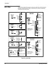
Menu Switches A4
4
FrontĆpanel menu switches are read by the Front Panel board and changes
in menu selections are sent to the processor system.
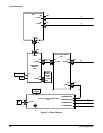
CPU A4
1
U101 is the frontĆpanel processor (FPP) and monitors the frontĆpanel conĆ
trols. It is a single chip microprocessor with builtĆin RAM, ROM, AĆtoĆD
converter, programmable timer, and serial communications interface.
The frontĆpanel processor reports any changes in state of the frontĆpanel
controls to the U201 on the A5 CPU board via the serial communication
interface.
The programmable timer TCMP1 (U101 pin 2) producesa0to5V,1kHz
square wave signal (CALSIG) that is used for probe compensation. TCMP2
(U101 pin 1) producesa0to5V,1kHzsignal that is converted to ECL level
(DITHER) by the resistive divider R503-R505. DITHER is used by the AnaĆ
log Signal Processor on the analog board.
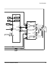
FPP Pots and Probes A4
1 2
The pot/probe scanner working with the AĆtoĆD converter internal to the
frontĆpanel processor digitizes the inputs and reports the amount a pot has
turned and the type of probe used.
Control lines to analog multiplexers U420 and U421 determine whether to
scan for pots or probes. If pots are to be scanned, one of 10 possible pot
inputs is read from either multiplexer U420 or U421. The voltage at the wiper
of the pot selected is applied to the frontĆpanel processor and digitized. The
amount and direction of change from the previous stored value is calculated
and sent to the host processor 68331 on the processor board.
The intensity and readout intensity pots on the front bezel are stopped pots
and represent one input each on the analog multiplexer U420. The other 8
pot inputs on U420 and U421 represent the 4 continuous rotation pots on
the front panel which are made of two wipers separated by 180 degrees and
contact a single resistive arc. Each continuous rotation pot represents two
inputs to the multiplexers.
Analog multiplexer U420 also selects one of the 4 possible probe inputs.
The probe code resistance from the P6139 probe is converted to a voltage
by pullĆup resistors R411-R414. This voltage is read by the pot/probe
scanner and the probe type is determined and sent to the host processor.
LEDs and Driver A4
3
There are 5 LEDs (light emitting diodes) on the front panel which are conĆ
nected between the outputs of an 8 bit LED latch, U202, and a pullĆup
resistor to +5 V. When a particular LED needs to be turned on or off, the