


Troubleshooting
TAS 455 and TAS 465 Service Manual
6Ć45
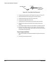
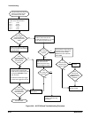
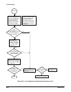
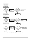
This procedure assumes that
there is front panel control.
Go to
Part
Two
Measure the power supply
voltages on J67 on the A1
Analog board.
Pin 12 +15V
Pin 10 +8.6V
Pin 9 -8.6V
Pin 6 +5.2V
Pin 1 -5.2V
Are
the voltages
approximately the
same as the nominal
value?
No
Yes
Turn the power off. Remove
the cable at J67 on the A1
Analog board and check
pins 12, 10, 9, 6, and 1 for
shorts to ground.
Yes
No
Are any
of the pins
shorted?
Replace the A1 Analog board.
Perform the A3 Display Driver
Board Troubleshooting
Procedure.
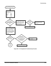
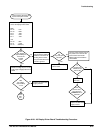
Press the CH1 button
and rotate the VOLTS/DIV
knob several times in
each direction. Repeat
for remaining channel(s).
Listen for clicks between
some of the voltage
ranges.
Were
clicks heard for
each channel?
Yes
No
Perform both to isolate
the problem.
Have you
performed both
the A5 CPU Board and the
A62 Front Panel module
Troubleshooting
Procedures?
Yes
No
Replace the A1 Analog board.
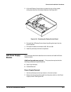
Figure 6Ć25:ăA1 Analog Board Troubleshooting Procedure