


Adjustment Procedures
TAS 455 and TAS 465 Service Manual
5Ć17
H Set INV to Off
H Set BW to Full
H Set the volts/div scale to 100 mV
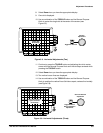
H Position the channel 2 display approximately 0.5 divisions below the
channel 1 display
12. Press the CH 1 button.
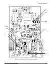
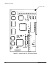
13. Adjust Ch 1 10X on the Analog board for the flattest response of the
most positive portion of the channel 1 waveform.
14. Set the channel 1 volts/div scale to 1 V.
15. Press the CH 2 button.
16. Adjust Ch 2 10X adjustment on the Analog board for the flattest reĆ
sponse of the most positive portion of the channel 2 waveform.
17. Set the channel 2 volts/div scale to 1 V.
18. Set the pulse generator amplitude to maximum.
19. Adjust Ch 2 100X on the Analog board for the flattest response of the
channel 2 waveform.
20. Adjust Ch 1 100X on the Analog board for the flattest response of the
channel 1 waveform.
21. Disconnect the test setup from the oscilloscope.
Vertical Gain Adjust (Cabinet On)
Equipment Required: None.
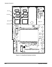
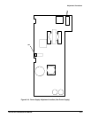
Adjustment Locations: This procedure requires adjustments to the Display
Driver board. See Figure 5Ć14 on page 5Ć19 for the location of the adjustĆ
ments.
Prerequisites: Low Frequency Output Compensation, Factory Vertical Cal,
and Attenuator Compensation adjustment procedures.
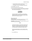
1. Slide the cabinet on the instrument and allow a 20Ćminute warm up.
2. Press the CURSOR button and set DVOLT to On.
3. Set the volts/div scale to 1 V.
4. Position the cursors 6 divisions apart, centered vertically and check that
the DVolts readout is between 5.96 V and 6.04 V.
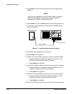
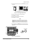
NOTE
If the readout in step 4 is within the limits given, stop here. The
calibration is complete.
If the readout is outside the limits, continue with this procedure.