


Removal and Installation Procedures
TAS 455 and TAS 465 Service Manual
6Ć25
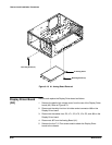
H Rear Cover Removal
H Cabinet Removal
H Front Trim Removal
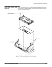
1. Set the oscilloscope so its top side is down on the work surface and its
front is facing you.
2. Disconnect the delay line from its holder and at connector J68 on the
Analog board.
3. Disconnect the cables at connectors J50 and J67 on the Analog board.
4. Disconnect the cable to the rear panel ZĆaxis connector.
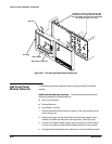
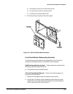
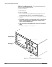
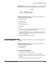
5. Using Figure 6Ć13 as a guide, remove the four TĆ15 TorxR screws securĆ
ing the attenuator assembly to the front of the chassis. Next remove the
four TĆ15 TorxR screws securing the attenuator board to the chassis.
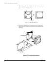
6. Lift the attenuator assembly away from the oscilloscope to complete its
removal.