


TAS 455 and TAS 465 Service Manual
6Ć41
Troubleshooting
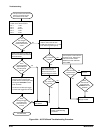
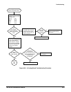
This subsection contains information and procedures designed to help you
isolate problems to a faulty module in the oscilloscope. If a module needs to
be removed for repair or replacement, follow the Removal and Installation
Procedures located in this section.
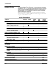
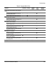
If the oscilloscope does not perform correctly, note each symptom or failure.
Next, refer to the Symptom Matrix Table (Table 6Ć5). Locate the symptoms
that most closely resemble the symptoms you noted. If there are multiple
symptoms, use a process of elimination to reduce the number of possible
faulty modules. Identify possible faulty modules, and then perform the
troubleshooting procedure/s indicated.
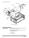
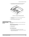
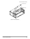
The cabinet must be removed to gain access to the modules for measuring
signals and voltages. Refer to the Removal and Installation Procedures
beginning on page 6Ć9 for instructions to remove the cabinet.
Table 6Ć4 lists the equipment required to perform the troubleshooting proceĆ
dures.
TableĂ6Ć4:ăEquipment Required for Troubleshooting
Equipment
Example
Test Oscilloscope Tektronix TAS 465
Digital Multimeter (DMM) Tektronix DM250
High Voltage Probe Fluke Model 80K-40
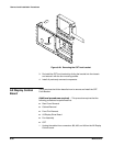
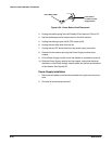
CAUTION
High voltages are present when the cabinet is removed. Do not remove the
high voltage shield from the A3 Display Driver board unless it is necessary to
measure the high voltage. Do not perform this procedure without the presĆ
ence of another person who is cable of providing aid.
Troubleshooting
Procedure
Equipment