


Troubleshooting
Maintenance
6Ć46
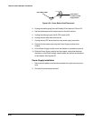
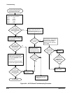
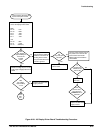
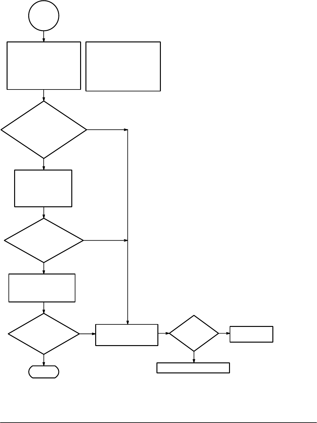
Put the oscilloscope in XY
mode. Select CH2 and turn
the readout intensity to
minimum. Measure the
voltage across the delay
line (J68) with a DMM.
No
Yes
Does
the voltage vary
between 100 mV to -100 mV
as the vertical position
knob is rotated?
Perform the A5 CPU
Board Troubleshooting
Procedure.
Yes
No
Is the
A5 CPU board
okay?
Replace the A1 Analog board.
Replace the A5
CPU board.
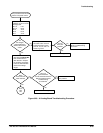
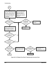
Select CH1 and
measure the voltage
across pins 16 and 17
of J67 with a DMM or
oscilloscope.
No
Yes
Does
the voltage change
as the vertical position
knob is rotated?
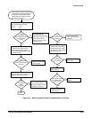
Rotate the Intensity knob
and measure the voltage at
pin 19 of J67 with a DMM
or oscilloscope.
No
Yes
Does
the voltage vary as
the position knob
is moved?
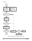
Note: In XY mode, a single
spot should appear near
the center of the CRT.
Reduce the intensity until
the spot is dim so that the
CRT phosphor will not be
damaged.
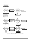
Done.
Yes
Part Two
Yes
Figure 6Ć25:ăA1 Analog Board Troubleshooting Procedure (Cont.)